http://www.farnell.com/datasheets/609430.pdf
Here above is a PNP transistor that not only will work at 400 V but has a 500 V peak ability. Ft and gain are far better than would be thought possible. If I was mad enoung to try I would use this device. It is also low cost and 700 mW. The gain states 300 if used near it's sensible limit, 200 if run with caution well below 100C. In a Naim clone it would be a very nice VAS choice if surface mount is not a problem. I doubt it would ever be thought of as an audio device. I have a hunch it will be fine. Cob is about 7 pF which is about right for a VAS. 2SB716 is from memory 2.5 pF. That's a world that no longer exists. This transistor is very close on the basics.
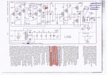
The Linn circuit ( Contrology Ltd ) is very crafty. Note the use of a bootstrap CCS so avoid needing a PNP. The op amp ( LM324 ) and BC 327 look unlikely choices in a 340 V circuit. They work fine. The biasing is a bit unusual. It looks a bit like a 1 watt JLH at 330 V. The power amp is to the right of my green dot showing input wave and magnitude. The distortion of the Vallhalla is about - 66dB which is an excellent result. All for nothing really as the motor can only draw current in the way the construction allows. If you turn the motor into an altenator with load you will see exactly the same waveform. Below is an example, a very good one as it has a nice order to the harmonics.

Here above is a PNP transistor that not only will work at 400 V but has a 500 V peak ability. Ft and gain are far better than would be thought possible. If I was mad enoung to try I would use this device. It is also low cost and 700 mW. The gain states 300 if used near it's sensible limit, 200 if run with caution well below 100C. In a Naim clone it would be a very nice VAS choice if surface mount is not a problem. I doubt it would ever be thought of as an audio device. I have a hunch it will be fine. Cob is about 7 pF which is about right for a VAS. 2SB716 is from memory 2.5 pF. That's a world that no longer exists. This transistor is very close on the basics.
The Linn circuit ( Contrology Ltd ) is very crafty. Note the use of a bootstrap CCS so avoid needing a PNP. The op amp ( LM324 ) and BC 327 look unlikely choices in a 340 V circuit. They work fine. The biasing is a bit unusual. It looks a bit like a 1 watt JLH at 330 V. The power amp is to the right of my green dot showing input wave and magnitude. The distortion of the Vallhalla is about - 66dB which is an excellent result. All for nothing really as the motor can only draw current in the way the construction allows. If you turn the motor into an altenator with load you will see exactly the same waveform. Below is an example, a very good one as it has a nice order to the harmonics.
I did try a triangle-wave to the motor and think it was 95% the same ( Triangle wave is F + 1/9F3+1/25F5+1/49F7.... ). The sine-wave was marginally better. My feeling is the sine-wave allows it to do it's own thing, albeit it is a triangle-wave. The big surprise is a square-wave is only marginally worse ( F + 1/3F3+1/5F5+1/7 F7..... ) One has to be very careful when trying as the torque verses vibration is the only real question. The current waveform into the motor tells all. It is mostly the same regardless of what is offered. The motor acts as a filter. My conjecture is loadspeakers are the same and mostly we talk nonsense about THD. What we don't want is crossover glitches or dynamic range dead zones as in worst case MP3. What we do want is any residual to be in nicely dropping harmonics. The wave I gave is nearing the tens of distortion. If fed into a speaker and a sensible volume it will still sound reasonably like a pure wave. The reason being it has ordered harmonics. Some examples are even closer to sounding pure yet have 10 % THD. Most of what you read is nothing like what you hear. Hi fi is a bit like fishing where the point is not really to eat the fish. That isn't really where I want to be.
People talk about current drive. Maybe it is better. Current measurements certainly say plenty. Naim were very interested in the current waveforms.
The Garrard motor is typically about - 52 dB. It is not a synchronous type. It will behave like a synchrous at light loading when constant torque. For that reason the stylus must always be the lessor torque. This is true of most turtables. As luck would have it the lubrication enforces that.
Now you know as much as I learnt in 40 years +.
It's a very long time since I experimented with my Thorens motor and drive voltage (1978?)
I think it would not start on 90Vac. It just sat there vibrating.
If one manually started it with a turn between thumb and finger it would run but was very rough. I did not try to run it at a much lower voltage since this roughness (around the 85Vac) would come through as flutter in the audio.
I ended up running at around 110Vac from a reverse connected 240:24Vac transformer fed with ~11Vac from a 50W power amplifier. I suspect it would perform better at slightly higher voltage, maybe 115 to 120Vac.
The circuit by Alan Ainslie was published in Hi-Fi News issue of June 1973.
Significantly the oscillator was a phase shift type making use of four germanium transistors (GBT41B or OC44) to cause two 90 degree phase shifts. The step up transformer was a 6.3 V filament heater type.
Germanium transistors were specified as the oscillator was stable without a thermistor to stabilise the loop gain. The design could be adapted to use silicon PNP's given due attention to that aspect. The power amplifier is a simple design also using germanium devices.
Speed was set by a divider networks in the feedback path - these incorporating a trim pot within each for fine adjustment with a switch to select the divider network appropriate to 33/45 rpm.
There was a detailed set up procedure to adjust the speed to match mains frequency.
There is an article in this month's issue of Australia's Silicon Chip magazine on checking turntable speed with a white LED strobe that shows some pitfalls of relying on mains frequency and some question marks about the accuracy of stroboscopic cards or the markings on the rim of a platter.
The preface to the article says " So you have dragged out the old turntable and playing vinyl again. Good. But how do you know that the turntable speed is correct?....."
Interest in vinyl is hotting up.
Last edited:
Now you know as much as I learnt in 40 years +.
I've also been building and experimenting for decades (maybe 1 less than you?), but I have to say that the Naim 22K collector resistor has been a major breakthrough in my thinking about the why's and wherefore's of amplifiers. It seems to have joined the dots in a pattern I tried to ignore for years!
The funny bit is if the Vbe of TR4 is wrong it isn't exactly as intended. Alas we don't really know what it should be. My guess is anything that takes it away from a 50/50 balance is likely to sound like a Naim. When the Vbe is 0.55V we are at only 55/45.
The TD125 had a two op amp Wien Bridge oscillator with lamp stabiliser for gain. Often the two op amp version was shown as the route to lower distortion. In this case it spreads the work load. The op amps had simple zero bias class BC output using transistors something like BD135/136 as current dumpers. There was loop feedback to help the crossover distortion a little. I suspect if 2 x 1N4148 bias diodes were fitted and 2 x 47K either side a better waveform would be had without extra heat output. Bias might be ideally <1.2V. A Wien will be about -60 dB set up like this. If the circuit fails WD40 sometimes is the cure.
My first Wien was using a RA 53 thermistor and 680R ( R A Penfold ). The RA 53 ( Bowthrope ) was the upper arm to the negative input. The other loop 66 nF and 47 K in both series and paralell giving the required positive side. That gives 51.3 Hz. A 5K trimmer to get 50 Hz. Later this was 10nF NPO and 300K and 50 K. The bulb type has the blub or lamp as I am told is more correct to the lower arm ( opposite temp curve to RA 53 ). My first op amp was LF351N and then TL071. NE5532 with the spare op amp used as a two pole active filter can be excellent. I mostly use one of those as my test oscillator. If I was prepared to do a little work I could get nearly -90 dB and still use NE5532. To do that it could only do spot frequencies. I have a low cost generator that is good for 5 Mhz. Perhaps my best bet is a State Variable Filter to add to it. I could chose some frequencies to focus on. The schools device does what look to be a perfect sine-waves. They are only good to - 44dB and nasty in harmonics. Even so the hard work is done and all that is required is a clean up circuit. NE5532 has a small advantage over NE5534, it is slightly happier as a unity gain inverting filter. If these are combined they do have slightly lower distortion due to common mode cancellation ( I believe and have observed ).
The funny bit is if the Vbe of TR4 is wrong it isn't exactly as intended. Alas we don't really know what it should be. My guess is anything that takes it away from a 50/50 balance is likely to sound like a Naim. When the Vbe is 0.55V we are at only 55/45.
Someone reported TR4 runs hot which raises the question of a reduction in Vbe commonly held to be 2 mV/mA for increases above 25 degrees C.
There can be exceptions to the general rule as discussed in an interesting article by well known (sadly late) industry figure Robert Pease - see page 4 at ftp://telescript.denayer.wenk.be/pu...analoog_e/bijlagen/transistoren/Vbe_stuff.pdf
The ZTX753 has a current gain of 225 at 10 mA.
The hot conditon also raises gain which is nice. Reading the SMD spec it says about 300 if 100C and 200 in general ( Quoted at - 10 V Vce! ). It raises from Vbe 620 mV to about 770 mV if run hot. Cob is 7pF . ZTX 753 has Cob of 30 pF . With care the Cdom could be lowered. Of the transistors avaiable if seems the logical choice and without any realtionship to linearity it should sound loads better due to what I would call better gearing. The Vbe seems to be about 610 mV for 10 mA. I suspect that will be what you will get. 910 R could be tried. That would be 67/33% approximately. It should sound better in terms of punch as a bonus. 10K added would do that.
Some were talking about quadrature in oscillators. The simplest way is to buy a capacitance meter which if like mine is good to +/-0.5% will be better than high cost caps. Buy some 10 nF cog caps ( COG beat any, should be 30 ppm ) . Calculate resistors required and build a series of 1st order filters. That is R ( 318K 50 ppm is fine like MRS25 ) from op amp out to next op amp in with capacitor op amp in to ground ( 10 nF if 50 Hz ). If using a square wave the 1st harmonic will be - 9.5 db down. You need -56 db better than that for safety. 300K+18K+10nF will give -7dB 100 Hz -10 dB 150Hz and - 3 dB 50 Hz. 8 sections give 8(10-3) = 56 dB . Every 2 poles you get 90 degress phase shift and half the gain ( - 6 dB ). If a 74HC4060 gives 2.5V rms we still have a reasonable output at the 6th pole of 0.4V. To keep it as simple as possible 2 x 10 K gain option to every 2nd pole will maintain the output. If you can not afford the cost of a capacitance meter tweaking the RC to give the exact voltage will be a good approximation ( 300K + 13K 15K 16K 18K 20K 22K 24K ). Even if a cheap AC volt meter the error is constant. Every pole should drop to 70.71% ( 1.768 V if 2.5 ). One I built like this was exact! The final test is lets say pole 6 to 8. If 2.5 V at each the resulatant is 3.54V. I will investigate the active version as on paper it is mildly better. I did note one I built recently had very low hiss. That is a bit odd as statistic cancellation works because random noise has no phase. It must be active filters do more than I guess, 50 Hz shouldn't do this ( maybe I switched the noise averaging on and not before, that's been known ). TL074 is a good choice. If using LM324 use a 10 K pull down resistor to - ve. It's enough to help. With LM324 keep levels in the 2.5 V rms area. The Valhalla has no precaustions and gives very OK results. I read the designers notes for LM324. They were very dissapointed with it's performance. 40 nV noise and tons of crossover distortion. Obviously someone got it wrong. It seems it might be a LM339 with class B output. The choice was made to sell it cheap and not refine it. What a good choice. I love the LM324. If the noise can be tollerated it can be forced to be a nice device ( headphoe amp ). The 10 K replaced with a current source to drive 32R 1V. This kills the crossover distortion as it is pure class A SE. LM324 makes a supurb comparator with source and sink ability ( LM339 will only sink, I seem to be able to hold 20 mA all day long with one ). It can hit thrails without damage or latch up, few can claim that. I love TL074 also. If all the inputs and outputs are joined it will work. Suddenly it has current and lower noise. No book on op amps would suggest this. TL074 should be OK. It's simple resistor output protection helps. The JFET's don't seem to mind sharing an input. Even so one NE5532 section will on paper beat it. The JFET's score on not loading the circuit . LM324 is not bad on that as it is a Darlington input ( TR1, 2 if the Naim ).
The 8 x 4 dB at 100 Hz will be useful. 100 Hz always seems to get in. The nice thing with passive filters is the Q is usually not important ( it is what it is ) and should not produce freak results as a Chebishev can. Having said that I always use Chebishev as designed with care they are ideal for single frequencies. The exception can be 100 Hz problems. Sometimes a " worse " Chebishev gives better results. That is a larger ripple compromise that just happens to dip in a helpful place.
This post covers two discussions whereas the interest for some might be in only one of these - mostly to do with the Naim 140 clone.
In your discussion of oscillators in two places you mention the need to keep things simple, you seem to be getting your ideas down in writing as they occur, and while you may understand what you are talking about, the message also needs to be as simple as possible. This does not have to be all words, a picture or diagram can replace a lot of that.
In your discussion of oscillators in two places you mention the need to keep things simple, you seem to be getting your ideas down in writing as they occur, and while you may understand what you are talking about, the message also needs to be as simple as possible. This does not have to be all words, a picture or diagram can replace a lot of that.
Last edited:
I am posting Alan Ainslie's speed control circuit.
The circuit requires a thermistor for use with silicon pnp transistors and these may be hard to find.
The problem with these is to do with stability due to drift with changing temperature. Precision op.amps such as OP-07 might be used to perform the same functions as the discrete component blocks. In a self contained unit a IC power module would be an improvement.
For what it is worth regarding earlier mentioned transformer issues, C14 and R19 form a suppression network on the de facto secondary winding of T2 supplying the motor.
At power switch off T2 core is still magnetised while connected to a motor driven by a platter in motion. When the magnetic field collapses as a result of this the change will induce a current in this winding. Better to suppress this at source to reduce induction into the de facto primary winding.
Attachments

This is the simplest way to draw it. The gain of the Wien must be >3. The author of this version has shown the minimum value. Seeing as it is diode stabilised I think 5K6 + 2K7 will serve well enough. The gain if so is 1+ ( 5.6/2.7 ) = 3.074. LED's will give a higher output and be less sensetive to temperature changes. If you know more about electronics you will know simpler ways which will be impossible for someone not willing to spend $300 on test gear. To be honest even then this design will be better as it is as near to ideal theory as it is possible to get. The near infinite input impedance of TL074 will allow theory and reality to reach textbook ideals. If a simple digital meter says an output of 1/root2 ( 0.7071 ) or 1 it will be correct. The reference being the Wien output. The blue to green outputs we require are two sides of a triangle ( any two green and blue if extending the idea to more poles ). Root ( 1 squared + 1 squared ) = 1.4142136 of the Wien output when correct. The Wien shown can give about - 40 dB distortion. This offers - 54 dB and - 61 db distortion typical when filtered ( sum of squares ). If the oscillator is one part of a a TL074 and one passive filter added to use up alll op amps one could then start the 6 pole version which would be perfection ( 6 + 1 ). If so the final ouput uncorrected would be 0.7071 of the Wien output. If a rocket to the Moon this will get there and land safely. The one 1% the Wien offers is already good enough. If you like after Christmas I will build and test a single TL074 version. You might want to go 6 + 1 pole to make it into a test bench oscillator for testing the Naim clone. It will be good enough. Remeber I said yesterday that 300K + 12 to 24 K might be used to get the meter right. That's all it needs to be textbook perfect. This is where I part company with most people. Textbook perfect is perfect. I was told by NASA as yet the physics of Newton is all they have used. I am that type of person. Never make a job more complicated than it needs to be.
The filter is specific to 50 Hz. As the parts are cheap another could be made for 45 RPM or 67.5 Hz. The reason the author didn't use 318K+ 10 nF is the calculated frequency starts to be different by perhaps 1% if higher values of R used. It won't help really as it will be a fraction off regardless. Best to adust using a strobe and use the NPO caps. The Linn or Thorens motors work upto 67.5 Hz and down to 50 Hz. Below or above that is gamble.
If starting with a crystal square-wave output from lets say 2 x 74HC4060 and 3.2768 MHz crystal use two passive filter stages. The blue would feed the pin 3 of the next group of filters. The motor will go forwards or backwards. Swap the wires to get what you want ( any blue or green set ). This filter can be set up using a cheap meter using geometry alone and yet be textbook correct.
Happy Christmas everyone. Here is something to think about. If text book correct it is already New Year. Happy that whenever it is and as they say " peace and good will ". Talking down the pub last night I put forward the maths for everyone being richer. It is simple. We share as best we can. A lady didn't get it although I am sure she did. I said " OK we love people enough to help each other ". I got a big smile.
Hi. Happy New Year to everyone.
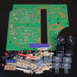
I received the NAP200 kit but without the schematic ;( The PCB is of excellent quality.
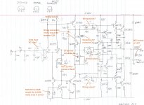
Using the PCB, I found the schematic and found a few possibles parts and/or connection errors. Maybe Nigel can comment on the things I found. Thanks in advance
SB
I received the NAP200 kit but without the schematic ;( The PCB is of excellent quality.
Using the PCB, I found the schematic and found a few possibles parts and/or connection errors. Maybe Nigel can comment on the things I found. Thanks in advance
SB
Attachments
Hi. Happy New Year to everyone.
I received the NAP200 kit but without the schematic ;( The PCB is of excellent quality.
Using the PCB, I found the schematic and found a few possibles parts and/or connection errors. Maybe Nigel can comment on the things I found. Thanks in advance
SB
Hi, good to hear that you've received the kit - I've ordered one also.
Out of interest what is the tolerance of the metal film resistors that have been supplied? The Nait 3 with NAC 90/3 that I currently have uses resistors with 5% tolerance.
Also in the NAC 90/3 the equivalent parts to those in your sketched circuit diagram (5K6 (TR2 Collector to +40V) and 27K (TR2 Base to 0R22 output resistor)) are 1% 50ppm resistors - are precision resistors included in the kit for these locations?
What is your feel for the authenticity of the power transistors? Do they seem to be genuine parts?
Thanks
Chris
I will have a better look as soon as I can, a bit bogged down with a project. Hopefully Andrew gets a look and Ian.
I will print out the diagram and get some values written down.
As many have said I don't really like or see the need for the networks between the VAS chain and TR7/8. I will look to see if it is similar in what it does.
There is a very odd coincidence with a item I intended to post today but didn't on another thread. I argued a TR1+2 current of 5 mA could match a VAS current of 5 mA and that as best as I knew never had existed. The arguement being a set of 2SC5200/2SA1943 possibly driven by the same would be a more modern way of thinking and not need so much VAS current.
The advantage in this version being that true transconductance might happen into the VAS transistor. If we call the VAS current 9 mA the TR4 Re = 26/9 mA = 2R9. That implies a typical Zin of 300R. That looks to be nicely matched to 270 R. Personally I would have gone further. It might be reasonable to add 2.9 x 3.8 = 11 R to TR4 emitter ( ZTX753 ). This would restore the loop gain to that of the Naim. It would raise Z in to 1400R. That's very nice. IM distortion should be reduced. In fact 5R6 would be more than OK. If the transistor had a gain of 300 as Japanese transistors can ( most are fakes I suspect now ) then this would be ideal without any resitor. With caution I like what I see. DC off set might be higher. Anything below 100 mV is OK. I know it is not clear cut how the transconductance works when a VAS so accept it can happen more easilly than I suppose. In valve designs they liked to see 3 to 1 impedance ratio. As this is a I to V converter it could be argued that none of this matters. This designer might have also played it safe and liked to have surplus current. It is offering a higher slew rate.
The writer on the other thread was saying he could hear an over sized TR1+2 current sounded better but had no measurements to prove it. I think it would be IM or more likely TID.
The 0R22 output resistor is spot on. Geofrey Horn claimed the only reason the Quad 405 sounded different was that resistor. He claimed to have fitted one to the 405 and could hear no difference via Quad ESL speakers. That is what we lack in reviewers. He liked the Naim and found out why. I suspect he wasn't very wrong. Damping factor is critical although not with the ESL. It is easier to start with plenty and loose some. It also makes the amplifier like the speakers a bit more ( makes the resulatant more resistive ). It migh interest people to know that even a damping factor of 3 offers some useful cone damping ( mid 1950's tests in Wireless World ). 0R22 d = 1+ ( 4/0.28 ) or about 15, I have added a bit for cable.
The Zobel ( 0.22 8R2 or 12 R) should be OK either way. I usually use 100 nF and 4R7. Some chip amps use 100nF 1R, that isn't a good sign.
The input filter is a bit odd. I think it will be OK.
39 pF for TR4 is low considering the loop gain . A good sign if stable.
Happy New year also to all.
Wow that was fast and already very interesting analysis and comments. Can't wait to have the schematic connection and values confirmed. I'll check the parts further tomorrow. I already ordered from an known good supplier and received output transistors that I plan to use instead of the supplied ones. I could compare them and see if they look ok, I'll keep them as spare if they are good, otherwise I'll just trash them.
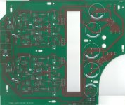
The ZTX, MPSA and MJE parts looks genuine. By the way there are marking missing for some of the input transistors (look at the PCB scan), but there is a bunch of MPSA06 transistors included. I put on myself to mark BC239C for TR1/TR2 on the schematic.
There is no instructions, BOM or schematic included. I'm happy to have the help of this forum to get the amp up and running.
What about the 47uF cap near the 2N5089 & 27R resistor? In all the Naim amp schematic I saw this cap is always across the transistor E & C, not between the emitter and the 27R resistor. Is it ok, or a PCB error?
Thanks again.
Using the PCB, I found the schematic and found a few possibles parts and/or connection errors. Maybe Nigel can comment on the things I found. Thanks in advance
SB
Happy New Year!
IMO, the circuit is OK. If I was you, I would give it a try as is. There are changes, but I don't see errors. If they've made copy from the original, this is the closest to the new circuit we'll ever come.
The CCS and the current in the LTP is the most serious change. 330//330 gives them resistor value that they probably couldn't find for cheap. I don't think the resistors are in series.
The input filter has an interesting addition that I would consider as fine tuning. 10pF is very little to do much else, and the added 1k in the input actually matches better the feedback for improved DC offset. The drivers R/C obviously are also re-tuned for the new driver transistors. This is speed-up circuit that also add some stability margin. I also found by measuring the older one that it has some interesting effect on static (DC) conditions. I wouldn't change the given values without measuring and testing extensively.
Thanks for posting the schematic, by the way!
I tend to make them matched. Maybe I'm wrong.I guess that the higher HFE for TR1 compared to TR2 still apply in this circuit?
In any case, if you don't measure at the intended operating current the whole hfe thing is more or less pointless. Measuring with the DMM tester gives decent results in removing "the bad apples" from a transistor batch, but not much for precise matching. You need curve tracer for that, or to build test circuit for the specific current.
Hi. Happy New Year to everyone.
I received the NAP200 kit but without the schematic ;( The PCB is of excellent quality.
Using the PCB, I found the schematic and found a few possibles parts and/or connection errors. Maybe Nigel can comment on the things I found. Thanks in advance
SB
In the hifidiy discussion, some people has thermo issue with this board if you follow the original thermo compensation scheme.
http://bbs.hifidiy.net/forum.php?mod=viewthread&tid=1120806&highlight=nap200
#269 has photo for the burned transistor.
#301 illustrate how to set the thermo transistor. He is the seller and designer.
Last edited:
- Home
- Amplifiers
- Solid State
- NAP-140 Clone Amp Kit on eBay