Niam claimed the LM317 was hand selected. The rejects returned to the supplier under the understanding they were not to return to Naim. I suspect the selection was for noise/stability. The CD players had many. Naim selected all parts. They were cheap good devices ( Philips MRS 25 in 5 % grade ( SFR ? ), Now Vishay ). The resistors in matched groups. Not because the amp needs that. So as to be exactly like prototype and save money into the bargain. J V said it was lack of testing which causes reliability problems. Thus at no cost each as prototype. The ladies at Naim testing and placing in boxes as to exact value.
I recently did a test of many regulators. LM317 is still very good. I didn't get to - 144 dB on any and didn't think I could. LM317 was only slightly worse than the best I could find ( that's real world rather than concept ). I built a descrete regulator. It was 3 db better and would look at 100 MHz. The LM317 is good to 1 MHz. The output capacitor takes care of > 1 MHz. The LM317 will tollerate a big capacitor unlike most. The other trick with LM317 is a capacitor on the gain setting resistor. 47 uF can be used if switch on time isn't too important, 10 uF is what most would use. Never fit a PNP pass transistor as it never really is happy. It will work on motors OK. LD1084 is a better choice. It measures in every way the same as far as I can tell and can work on slightly less voltage. Many low drop out regulators do use an internal PNP device with collector output ( or NPN if negative type ). They usually have warnings about stability capacitors. My feeling is this will be heard. I seem to remember LD1084 isn't like that which is hard to understand when it works at low voltage. For whatever reason it seems very stable.
If you ever need to build a cheap very low drop out regulator of supurb stability do this. Have a raw DC to a fast power transistor , NPN for positive. Use a capacitor coupled input voltage doubler to a LM317 ( circa raw DC x 2 ). Feed the base of the transistor via a small resistor and capacitor ( 4R7 , 100 uF perhaps ) using a text book LM317 set up as the transistor bias. This should help protect the transitor and loose minimal volts. The LM317 will be locked at about 1 V above the NPN emitter ( 25 V = 24 V ). It will in every way out perform what is usual and might give 7 amps if needed. This should better anything typically used at very low cost. The 4u7 and 100 uF doing a fine job. There is no loop feedback which helps. OK the output impence is higher which is slightly worth questioning. I doubt it has real world problems if a capacitor is added. The 4R7 sould allow the capacitor to charge without harming the transistor. Also most big transitors will tollerate 2 amps through the base, it is in most spec sheets. The LM317 should limit to about 2 amps depending on make. As there is no loop feedback path stability shoud be excellent. The arguement against all series regulators is they take part in the amplification. With this one almost not. I doubt any shunt regulator is better. The idea of shunt is great. I doubt if that ever becomes reality.
The 317 seems to be a LM7805 of 1.25 V. The LM7805 can be used as a variable regulator in multiples of 5 V rather than 1.25. The big advatage is the the noise is always a percentage of the output voltage. If no capacitor is fitted the two devices are mostly the same. The capacitor shunts the noise to ground. Thus the noise is about 20 times less than a LM7824 or >20 dB. Seeing as this advantage costs pennies it is one of the best in audio. Remember the LM317 is less likely to cause problems if no scope available than " better " choices. LM317 is said to be a LM741 with voltage reference. An NE 5532 in tandem will give about 2 nV ( 20 db less than LM317's op amp ). A LED is an OK reference. A Naim clone NPN pass transistor will be about 0.7 nV. Don't use feedback to the pass device and a capacitor to the LED will get you a Naim beater that shouldn't cause trouble. The voltage is standard gain formula ( 1.7 x X = 24 V ). The 5532 will be OK at 30 V.
Anyone wanting to look at this needs to know it is of prime importance. I did a lot of work on regulators and thought I would like to pass it on. Most of what I read I don't find to be true.
When I shorted the 22K TR2 collector resistor I observed marginally improved transient response behaviour - not enough difference to indicate that compensation is the reason for the resistor being there.
I suppose I ought to measure the distortion profile with and without the 22K, it would be interesting to quantify its effect.
My curiosity is over Ian Finch's supposition in post #1426 about selective cancellation of harmonics and others' comments about second harmonics.
Naim used some pretty savage test loads for their amplifiers so it would be interesting to see some results with your NCC200 with and without the 22k resistor on a 10 kHz square wave into 8R+2uF.
Returning to TR2 in harness with the 22k collector load resistor - The base of a transistor occupies a distance between two depletion layers separating it from the collector on one side and the emitter on another. The emitters of TR1 and TR2 are both connected to the same fixed voltage source and ignored there being no point of difference between TR1 and TR2.
According to E.M. Wolfendale in "The Transistor" the width of the collector depletion layer is directly proportional to the applied voltage.
We have around 30 volts at TR1 collector and 10.78 volts at TR2 due to the 22k collector load - it can be said that the collector depletion layer for TR1 is wider than in TR2 due to the difference in applied voltages.
When the collector depletion layer in a transistor is made as wide as practical the base is made increasingly narrower. TR1 fits this model.
If the collector depletion layer is decreased by lowering the collector voltage the base width is increased and more current can flow through the base junction.
As I.e, a fixed quantity =I.c+I.b, an increase in I.b. will cause a reduction in I.c. and the ratio of I.c./I.b. (current gain) will decrease regardless of the capability that spec sheets may indicate - say 300 for a BC546
We have this with TR2.
As far as collector currents go transistor Ic/Ie or alpha = beta (transistor current gain)/ beta +1.
A heavy reduction in TR2 current gain to a value of 49 will still result in 98% of the emitter current being passed through the collector so the sharing of current between TR1 and TR2 would remain relatively close.
The formula is a simplified one that ignores external resistance in series with the emitter or collector as short circuited - a point to remember if applying this to TR2. I would be interested if anyone has alternative explanations.
There is nothing wrong with investigating circuit design aspects by taking voltage measurements - it is a common practice for manufacturers to record voltages on circuit diagrams in repair manuals to assist technicians to diagnose the causes of faults.
I think that has a small contriubution. Maybe overlooked is the imbalance is a more genreous output current as a bonus ( 700mA + 300 mA if 1 mA, 500/500 when balanced ). The curve of a transistor is much like a pentode for the reason both are transitional resistance devices. I think the connection is tenuous as the way things work is different. The curve looks similar. It was described to me as the old mathamatical paradox of halving the distance to an object by each step and never arriving. That's how transitional resistance should be viewed. That's the type of curve we can start to find. People will say some transistors are more linear. No, more exponetial. By shifting the long tail pair current distribution we allow the full exponential curve back in. Thus we have the DC servo of an op amp and the sound of a single transistor. A single transistor can be made to DC servo. It needs very large capacitors in the feedback arm to retain simplicity. It's not easy. I have a design as workable concept if anyone wants. I doubt you should.
As I said before J V would have been given an amp with two terminal posts per amp. He soldered in resistors until he got the sound he liked. I suspect that was with Quad ESL 57 and his own tape recordings. I visited Salt Lane just after he set up and had that conversation.
As I said before J V would have been given an amp with two terminal posts per amp. He soldered in resistors until he got the sound he liked. I suspect that was with Quad ESL 57 and his own tape recordings. I visited Salt Lane just after he set up and had that conversation.
The Valve Wizard -Small Signal Pentode
This is the type of valve that almost was a transistor, the EF86. Most transistor pentode converstions leave out the more likely bipolar devices that the world and Naim use. Well worth a read of how the old world worked. This site is so much better than most. It is intended for musicians. I would say don't use EF86 as good examples are hard to come by. ECC82 in cascode more useful and not too complicated ( heater V2 is the problem and voltages, + 100 V is OK ). The valve cascode is another part of the transistor cascode story. The classic valve is a triode which has no direct transistor analogue. However the cascode is not too far away from both pentode and bipolar. Some will reject that. I can see why. ECC86 in pentode has almost the low distortion of the triode version and massive voltage swing. That is almost magic. That is without any loop feedback and little feedback of other sorts.
If an EF 86 is used with shunt feedback to give 3180/318 uS and a Denon DL 110 pick up with a 470 nF shunt that would be my conceptually perfect phono stage. As the pick up needs EQ why not get everything done in one hit. The DL110 is the only pick up I know of that will do direct 75 uS EQ. The output could be fed into an op amp as > 470 K loading is required. OPA2604 would do and should not over cook the noise problems.
If that caught your imagination the Leak is as good a design to copy as I know of. The feedback needs simplifying as microphones and tape head circuits are not required. If valve two was the op amp take the 330 K to be the output impedance ( it will be lower). If so 1M would be minimum input impedance.
http://www.diyaudio.com/forums/tube...-phono-preamplifier-shematic.html#post2250779
http://www.diyaudio.com/forums/tube...-phono-preamplifier-shematic.html#post2250779
I think that has a small contriubution.
I felt compelled to answer Dave S ' question whether I was observing or speculating over his d.c. measurements. To answer this I looked into the unexplained but small discrepancy between the collector currents for TR1 and TR2.
Although some more measurements could be taken to confirm this, those recorded suggest a tenfold increase in TR2 dc base current in relation to TR1.
To continue this line, the 27k nfb resistor allows TR2 base dc current to flow to a zero point at the output , in addition to passing voltage signals from the amplifier output in the opposite direction. While this is a normal state of affairs there is a point of difference in terms of a tenfold larger dc base current.
There is an electrolytic capacitor in the decoupling arm of the nfb network. In a single supply rail amplifier this capacitor would have a decent voltage on the positive connection.
There is a parasitic non linear resistance in series with the capacitance and amongst other things the value varies with the voltage applied, temperature is another - a possible reason for Naim recommending their amplifiers be left on at all times.
A constant dc voltage across the decoupling capacitor seems more likely with an increase in TR2 base current.
I will look over the points you made and come back to these later.

The reason the Naim of the 1970/80's needs to be left on as Douglas Self so correctly says is the inability of the bias setting transistor to match initial conditions and stasis point ( the latter the more important ). The bad news is the Self version isn't really 100 % either. The NPN NPN output stage makes it worse. In my opinion these kit amps will be a long way from ideal as no two will have the same conditions of stasis. That is when the heat leaving the amplifer and the biasing are matched and include sound preferences. It will make a big difference as to how the amplifier sounds. This also complicates one builder advising another. My advice would be run the amp hot enough to sound pleasing. Be careful it's not getting too hot when no music playing.
As to long tail pair mismatch. It is the obsession of most writers, that seems to mean it is not as wonderful as it's ease of use suggests. This man has gone into more detail than most. I suspect this amp is well worth trying.
MJR7-Mk5 Mosfet Power Amplifier
As to long tail pair mismatch. It is the obsession of most writers, that seems to mean it is not as wonderful as it's ease of use suggests. This man has gone into more detail than most. I suspect this amp is well worth trying.
MJR7-Mk5 Mosfet Power Amplifier
Nigel, D Self's designs for simple EF and CFP design bias systems are remarkably stable and precise if implemented as described. I've not seen any of his efforts at a bias controller for QC designs like the Naim, where no bias can be considered correct, so what are you referring to?
Indeed, MJR's designs are inspiring pieces of work and break new ground in some areas. We are however, straying off again onto other topics and interests with that design that has very little in common here though.
Indeed, MJR's designs are inspiring pieces of work and break new ground in some areas. We are however, straying off again onto other topics and interests with that design that has very little in common here though.
Yes and No. Self's solutions are better than most. Overbiasing seems to work better. I think his gain doubling thing is a red herring and could make for rather dry sounding amps. Better is to overbias and set the distortion to the place where our ears don't mind too much. 1 watt is the start point.
In a strange way Self comes to the same idea in his very intelligent class A/C design. He makes the switching points so high as to be mostly unimportant. I found if I made the class A amp 5 watts it was fine.
Self also says the overbiased class AB as class A is ideal. This means 90% of the time it is class A. If something weird happens it becomes a version of class AB he likes less ( like Naim ). I think that's where most Naim builders can side step what Self says. A critically set, overbiased class AB is still valid.
MJR. I think it shows where most of these question will go as a sign post. The Naim kits are sort of OK. Before going too far it is good to look at other ideas. At face value the MJR design is from an idiot ( not me saying that ). He is doing nearly everything wrong ( again not me ). Well that isn't born out by the results he gets. At a guess 90% of what is held to be unquestionable is simply wrong and MJR is the proof. The design is closer to the 1957 H C Lin amplifer than is thought good design practice. And yet it shines. ESP Audio El Cheapo is as far as most got with the Lin design. Rod shows a few variations. People at DIY Audio can get very snotty about ESP Audio. I haven't a clue why? The only thing on the internet that I can totally relate to. Like me he likes simple designs that work. His FET amp works upto 10 kHz with zero bias!! 3 mA in fact as FET's never switch completely off. That's not bad and has some relationship to the MJR design.
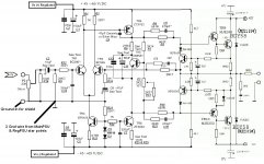
I'm posting the schematic again as a reference to what this is about which is the trick of imbalance of the input stage. I've done some quick and dirty Spice modelling in TINA and come up with a few relevant DC currents there that may interest mjona. Not that they can't be calculated but this is perhaps easier if more is required.
Note that I cheated and only the input stage and VAS were modeled, the output stage being disconnected and feedback taken directly from TR6 collector via the same 27k feedback resistor. As modeled there is just 0.5 uA there and I used BC550C and MPSW92/42 models as appropriate. The currents listed are those in the associated resistors which unfortunately aren't numbered on the schematic. It should still be easy enough to see what the DC conditions are and what degree of imbalance is likely.
- Rail supply voltages +/- 40V
- TR1 collector 0.743mA, TR2 collector 0.181mA
- TR3 emitter 0.982mA, TR6 emitter 7.6mA
An externally hosted image should be here but it was not working when we last tested it.
Note that I cheated and only the input stage and VAS were modeled, the output stage being disconnected and feedback taken directly from TR6 collector via the same 27k feedback resistor. As modeled there is just 0.5 uA there and I used BC550C and MPSW92/42 models as appropriate. The currents listed are those in the associated resistors which unfortunately aren't numbered on the schematic. It should still be easy enough to see what the DC conditions are and what degree of imbalance is likely.
- Rail supply voltages +/- 40V
- TR1 collector 0.743mA, TR2 collector 0.181mA
- TR3 emitter 0.982mA, TR6 emitter 7.6mA
In think that shows an unexspected bonus as the drive current is higher than the circa 490 mA the balanced version would give. Not a great advantage to be clear.
I think it shows that simulation has its limitations and that measurements of a real circuit and prodding around with a meter and a scope are much more useful.
FWIW I have built an "005CCN" which is the same topology except the "other way up" i.e. the IPS uses PNPs and the VAS is an NPN (MJE340). The OPS is a standard complementary double. The layout is completely different to the NCC200. I have included some of the Naim tweaks though, because I want to try to figure out which tweaks provide which sonic flavour. Its interesting to note how differently this biases up, I think the ZTXs (not used in this amp) have some rather unusual characteristics.
On a different note - I think the NCC200 is a great sounding amp, but perhaps just a bit too much sonic MSG for my tastes.
The ZTXs have been exhumed for discussion several times in this long thread. The most obvious distinction from other small signal types as VAS transistors is their exceptionally high Cob of 30pf and this variable capacitance isn't easily swamped by a much higher fixed Cdom and so keep distortion under control. The Cob of these transistors is in parallel with the fixed compensation cap, Cdom, so it figures high in the usefulness or otherwise of VAS transistor types.
The trend for many years now has been to adapt high linearity CRT video transistors like the BF467-70 series or KSC3503/A1381 - mainly because they do or at least did combine very low Cob with medium power rating and so permit something larger than shoebox amplifiers that are capable of even lower distortion.
Amusing analogy - "sonic MSG" but it does fit these amplifiers and many other concoctions that many seem to prefer to standard designs where the goal is least, rather than tweaked distortion. The ZTXs seem to result in the best traditional Naim sound and are an obvious feature in what look to be earlier versions of Avondale's NCC200. 'Always wondered how many changes L.W. could make to the schematic with not even a hint of issue date or revision status.
This comppany has good choices ( see other devices they do). It was a larger list alas. BF720/721 seem the modern devices. Put wires on them then heat shrink. Often they are used in cascode.
Medium Power-Driver
Medium Power-Driver
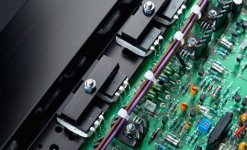
I have a little trouble in the testing process diagram that is when I use the same source + - 40 V DC for the whole system , all problems peacefully , but when I use steady pressure source for stories and separating the head of the DC voltage output to the speakers , even when using the general 1 through 2 sources that use diodes to the first floor level for that problem also occurs speakers DC , now I can only using dc 1 power supply for the entire system , someone could explain me what causes so sincerely thank
Attachments
I can't follow your description, MrThanh. Perhaps you mean that you have problems with getting both channels to work properly together? Does this cause hum? Do you have 2 separate dual power supplies (i.e. dual mono)? If so, you could have a hum loop and maybe need to make sure the signal socket grounds and the power supply grounds are insulated from the chassis and only make connection once, at the star ground.
You may also be saying you have ground-lifting diodes too, but I can't be sure. There are other possibilities but tell us more about the problem and if you agree with this or not. Perhaps you could also tell us what signal source you are using and how it is connected.
You may also be saying you have ground-lifting diodes too, but I can't be sure. There are other possibilities but tell us more about the problem and if you agree with this or not. Perhaps you could also tell us what signal source you are using and how it is connected.
Amusing analogy - "sonic MSG" but it does fit these amplifiers and many other concoctions that many seem to prefer to standard designs where the goal is least, rather than tweaked distortion.
What would your idea of "Saccharine Blur" be then?
😀 I've heard a few unprintable ones but that's rather cute. I'd relate it to a guitar pedal I used at one time, based on awful germanium transistors of unknown type. That had potential to soar like Carlos Santana with its prodigious amounts of H2. 'definitely a sweetened blur."Saccharine Blur"
- Home
- Amplifiers
- Solid State
- NAP-140 Clone Amp Kit on eBay