I had help from Europe to get the power transformer 😉
This Cie, Tiger in the UK doesn't ship internationally. You need a local contact to forward it to you...
It costed me around 40GBP for the shipping to Canada, about half the transfo price.
I asked Plitron for a custom transformer but they were not interested unless I order ten of them... I would have to replace the standard voltage transformer with three separate ones to get the same dual CT 28V secondaries + the 24V for the preamp section. All in all the custom transformer from UK + shipping was cheaper than three separate transfo of the same rating...
SB
Interesting. What sort of Hfes were the Naim BC239Cs?
Have you compared the sound of the Naim and the clone?
The BC239Cs were taken out of my Nait 3 (NAC 90/3 power amp)
The power amp board in the Nait 3 is of very similar circuit design to the NAP200, although the LTP current is lower and the output transistors are different.
Using my basic transistor tester, Hfe of the BC239Cs was measured at 437 (TR1) and 455 (TR2) for one channel, then 711 (TR1) and 688 (TR2) for the other.
The audio comparison I've made is between the Nait 3 and the NAP 200 clone - I don't have access to a genuine NAP 200. My current setup is now the pre-amp stage of the Nait 3 fed into the NAP 200 clone, the Nait 3 pre-amp is powered by the 24V output of the NAP 200 clone (I populated the voltage regulator section of the clone board).
I find the Nait 3 and NAP 200 clone to have a very similar character (I guess the 'Naim sound'), but with the clone there's a greater level of precision and detail that the Nait 3 just doesn't have even though I'm using exactly the same pre-amp. The switch to LCR polyester capacitors in the clone took this to another level yet.
Attachments
Last edited:
Quad FM3 like mine on Radio 2. Nice. It has Mono out if you need it. Sometimes in the past that was useful.
The hFE seeing as the LTP is biased away from balance shouldn't be an issue. Try 2 x 5R6 ( TR4 emitter ) when you do. Don't get too involved as to why it sounds different. There are a few things going on. Just see where it goes. 22R is about as far as I would go. 16R is a value I have used. I like classical music although listen to 70 % not classical. Being a snob I suspect the classical rules the choice. That works for voices also, so perhaps not so much a snob. If a scope is available one could bootstrap the 5R6 or whatever with a capacitor. As no one here has put this on a simulator ( ???? ) one should be very careful. As loop gain runs out at HF a small capacitor might be all it needs. 16 R is about 10 uF 1 kHz. The phase shift produced might make it a risk. When just a resistor it makes the amplifier more stable.
The hFE seeing as the LTP is biased away from balance shouldn't be an issue. Try 2 x 5R6 ( TR4 emitter ) when you do. Don't get too involved as to why it sounds different. There are a few things going on. Just see where it goes. 22R is about as far as I would go. 16R is a value I have used. I like classical music although listen to 70 % not classical. Being a snob I suspect the classical rules the choice. That works for voices also, so perhaps not so much a snob. If a scope is available one could bootstrap the 5R6 or whatever with a capacitor. As no one here has put this on a simulator ( ???? ) one should be very careful. As loop gain runs out at HF a small capacitor might be all it needs. 16 R is about 10 uF 1 kHz. The phase shift produced might make it a risk. When just a resistor it makes the amplifier more stable.
Try 2 x 5R6 ( TR4 emitter ) when you do.
Nigel, out of interest what is the intention of adding a resistor here? Why would this be advisable?
It's to painlessly shift the Vbe of TR4 up so as to swing the balance from 1.85/1.7 mA. I suspect it isn't enough when that . The 5R6 will go some way change to that. 10 mA at 5R6 = 0.056V. If TR4 sits at 0.5 V we get to 0.56 approximately. Using 11R2 we go to just over 0.6V which is a more usual figure. Seeing as Naim choose to do this why shouldn't you also choose?
You will loose a little loop gain. As this kit is a healthy version in tems of current with no LTP degeneration added we have scope to play. I will resist saying what you will hear. It should be interesting. In the book of beliefs of power amp engineering this is a no-no. In reality it can be very good. The no-no is they have made their minds up it is a transconductance stage. 99% it is. the 1% matters and can with good use of ears be tweaked. The reason it can made better is the stablity is a factor. More stable can sound very different to marginally unstable. It is hard to say which you will prefer.
I am a bit late going out the door so forgive typos.
Well I certainly prefer 10R emitter degen in the VAS in my 002CCN amp over zero (I adjusted TR1 collector resistor to maintain current balance in the LTP).
I prefer no emitter degen in the LTP.
Stability is not compromised by any of these changes, so I conclude the sound changes for some other reason.
I prefer no emitter degen in the LTP.
Stability is not compromised by any of these changes, so I conclude the sound changes for some other reason.
That's exactly as I see it. Safe fun. That's what the thread is about. At some point any of us are trying something new when playing with amplifiers. Safe is when it is fun.
I bet someone will prefer 12 R over anything else. Where is the harm in trying ? The words that might be used are punch and sweetness. They compete. At a point too high you get neither ( 47 R ? ).
I bet someone will prefer 12 R over anything else. Where is the harm in trying ? The words that might be used are punch and sweetness. They compete. At a point too high you get neither ( 47 R ? ).
That's exactly as I see it. Safe fun. That's what the thread is about. At some point any of us are trying something new when playing with amplifiers. Safe is when it is fun.
I bet someone will prefer 12 R over anything else. Where is the harm in trying ? The words that might be used are punch and sweetness. They compete. At a point too high you get neither ( 47 R ? ).
Interesting!!
I heard:
Shorted 47R LTP resistors = improved 3D soundstage and more coherent sound
Added 10R VAS degen = more rhythmic drive and coherence
Like you say, non of this stuff is in the text books. They just seem to be obsessed with THD reduction.
I will give my view of this. In 1947 the 19 year old DTN Williamson designed a landmark valve amplifier. Leak already had the TL12 on sale doing similar things. The Williamson was designed for DIY build. If you ever hear a correct Williamson ( I don't think most are ) get ready for a surprise. It sounds much like a transistor amplifer. DTN was given the project as other engineers were doing war work. DTN stated he didn't like to go below 1:3 impedance ratios of output impedance and the inptut of the next stage. Given the chance 1:10 is wise like preamp to power amp in.
Whilst one can not related the 1K of the Naim into what might be 300R of the VAS 1:0.3 loooks a bit of a chalenge. Now from DIN signal inputs I can see it can work. That is the input is current drive. Where it seems to get sticky is 1:1 ( transconductance ). Although it it very hard to prove IM distortion could be improved by optimum matching. With the Naim design it becomes a Venn diagrame of at least 4 intersecting possibilities. LTP balance realated to Vbe, Zin , stability seen as ringing and heard as similar reduced, optimum loop gain. People talk about slewing. Seems to me it's the same stuff with a more logical reason. The assumpton is the LTP to VAS is pure current drive. This ignores the fact the voltage waveform is very highly distorted into VAS base. Whilst I agree this by some miracle cures it's self. It begs the question is that false voltage waveform saying something? In a CD player we have similar issues using a I to V converter ( almost a VAS ). I suspect that is also a question many do not ask. I to V converters exist in valves also ( see RH34, ECC81 forced into current drive using shunt feedback ).
Whilst one can not related the 1K of the Naim into what might be 300R of the VAS 1:0.3 loooks a bit of a chalenge. Now from DIN signal inputs I can see it can work. That is the input is current drive. Where it seems to get sticky is 1:1 ( transconductance ). Although it it very hard to prove IM distortion could be improved by optimum matching. With the Naim design it becomes a Venn diagrame of at least 4 intersecting possibilities. LTP balance realated to Vbe, Zin , stability seen as ringing and heard as similar reduced, optimum loop gain. People talk about slewing. Seems to me it's the same stuff with a more logical reason. The assumpton is the LTP to VAS is pure current drive. This ignores the fact the voltage waveform is very highly distorted into VAS base. Whilst I agree this by some miracle cures it's self. It begs the question is that false voltage waveform saying something? In a CD player we have similar issues using a I to V converter ( almost a VAS ). I suspect that is also a question many do not ask. I to V converters exist in valves also ( see RH34, ECC81 forced into current drive using shunt feedback ).
Algar;/hifibluedevil you have mail
I didn't get any email from you, might have gone into junk box. Please send me a PM first.
thx
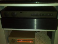
I received my custom power transformer and I'm very pleased. Transformer specs were:
Power rating: 450VA on 600VA core
Primary: 2 x 0-117V @ 50/60Hz
Electrostatic screen
Secondaries: 2 x 28-0-28V @ 3.57A rms + 1 x 26-0-26V @ 0.96A rms
GOSS band
Regulation: approx 5%
Estimated dimensions: max 75mm high
Mounting: insert in a potted centre
Leadouts: approx 400mm long flexible (stranded)
Black nylon tape covering
Here the test results with Line voltage 120V, 60Hz
Vout max (1kHz), in 8 ohms = 25Vac (78W), in 4 ohms = 22Vac (121W)
Vin max = 0.91Vac, in 8 ohms speaker load
Gain = 28.8dB
Output DC offset < 8mv
BW (Ref 1V, 1Khz) = 56Khz
THD (1V, 1Khz) = 0.01%
Supplies are at +/-42Vdc, 13mV ripple
At full power supplies drop at +/-38.8V
Last edited:
Algar,
I wonder if the pre-amp supply 26-0-26 can be used to power a led which can be installed on the front panel? Or, I may use the DC regulation for the preamp which is already on the board to power a led (with a dropping resistor in series)?
thx
I wonder if the pre-amp supply 26-0-26 can be used to power a led which can be installed on the front panel? Or, I may use the DC regulation for the preamp which is already on the board to power a led (with a dropping resistor in series)?
thx
Algar,
I wonder if the pre-amp supply 26-0-26 can be used to power a led which can be installed on the front panel? Or, I may use the DC regulation for the preamp which is already on the board to power a led (with a dropping resistor in series)?
thx
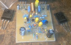
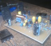
There is actually a space on the PCB for a resistor and LED, so yes that's part of the design. 🙂
Have a look at the bottom of the images in this post and you'll see.
Last edited:
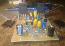
Hi, still using drivers MJE243/253 and MPSA06 as CSS with 2SC5200 outputs(h-140 modified ebay kit).
Amp is alive and stable for a year soon... bass still lossier then with TIP's/ BC550 CSS combo.
Mids are awsome(huge drums)... high's are kinda distorded.
I came to conclusion:
Stay with TIP's as drivers and BC550 as CSS if you want less distortion, more FLAT sound.
You guys got really active lately in this thread... was exiting to read 😀 Meanwhile, i got very close Naim NAP 140 PCB ready and populated. Still trying to fight against its and but's in terms of sound, especially missing protection which gained its importance lately 😀
Will the original naim nap 140 play good with ONE shared PSU ?
Renu
Attachments
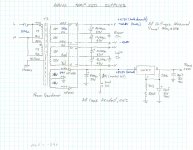
Here the supply schematic, with voltage readings, very simple supply really. With both channel supplies connected, at 30ma bias, the supply voltages settle at +/-41.3V, pretty close to the target of +/-40V.
Algar,
I wonder if the pre-amp supply 26-0-26 can be used to power a led which can be installed on the front panel? Or, I may use the DC regulation for the preamp which is already on the board to power a led (with a dropping resistor in series)?
thx
There is actually a space on the PCB for a resistor and LED, so yes that's part of the design. 🙂
Have a look at the bottom of the images in this post and you'll see.
The front panel LED is shown with the 10k fed from the ~39V supply.The led resistor is marked 4K7, I prefer 10K with a green led. SB
Expect the diode current to be ~(39-2)/10k = 3.7mA
4k7 would pass ~double the current.
You may find that 15k to 27k may give an acceptable brightness.
- Home
- Amplifiers
- Solid State
- NAP-140 Clone Amp Kit on eBay