Is any one familiar with nakamichi ta-3a remote controlled volume
Circuit. All functions work when using remote except volume. I thought it was a bad motor. Put motor from tested "parts" ta-3a. Just noticed motor is not getting any voltage from logic board when volume up or down is pressed.
Could it be one little transistor or something more sophisticated. I see few Toshiba branded large transistor chips on logic board
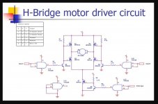
Most such controls have the motor connected to what is called an 'H Bridge Driver' which is simply a circuit that allows the motor to be supplied with either polarity of voltage in response to a logic drive signal.
First make sure the remote is transmitting OK... use a digital camera to view the IR LED.
Next up would be to determine the drive arrangement (the H Bridge) and locate the appropriate ports from the uProcessor/logic board and check with a scope (or even a DVM looking for 'change' as a key is pressed).
Start simple with the remote before going deeper... and has this worked in the past? and is the remote known to be the correct model for the amp?
This example uses FET's although most just use bjt devices.
Attachments
It's an eBay unit.. like most eBay units it comes with hidden issues.
I just tried using remote today
I put a motor from ta-3a that I know for sure works. Using original ta-3a remote which works perfectly on other ta-3a and ta4a
I found volume control driver on logic board(u506)
And q526 transistor. Which looks like the transistor doing voltage switching.
Hm. Might swap logic board now) would not be a big deal but I actually use remote quite often.
I hope it's q526 transistor.
Attachments

Last edited:
The diagram isn't really clear enough to make out fully but yes, pins 2 and 3 look to be the logic inputs. Just look for change in voltage as you hold the remote keys down.
Q526 looks to be a simple regulator. Can't make the voltages for sure but it looks like 6 volts on the zener and you should have nearly that on the emitter of the transistor feeding the chip. If those voltages are OK then its not the transistor... but check them as you press the remote key.
Q526 looks to be a simple regulator. Can't make the voltages for sure but it looks like 6 volts on the zener and you should have nearly that on the emitter of the transistor feeding the chip. If those voltages are OK then its not the transistor... but check them as you press the remote key.
I turned off the amp with remote. So it sort of was on (orange led light )
Not completely off. And now motor is working after 7 hours of being plugged in. Weird
I once had similar issue with phono not imidietly working on a luxman r115.
Phono starts to produce sound 10min after power up
Is this diode related? I've heard diying diodes work when warmed up
Not completely off. And now motor is working after 7 hours of being plugged in. Weird
I once had similar issue with phono not imidietly working on a luxman r115.
Phono starts to produce sound 10min after power up
Is this diode related? I've heard diying diodes work when warmed up
It is weird... and I've no idea tbh. You can't second guess faults like this, you have to make measurements and see what happens when it works compared to what happens when it doesn't (things such as looking at the appropriate pins of the chip with a scope).
I agree) it's very time consuming.
One day might have a scope. Learn few things. At the moment tinkering swapping boards around.
One day might have a scope. Learn few things. At the moment tinkering swapping boards around.
- Home
- Amplifiers
- Pass Labs
- Nakamichi ta-3a volume motor not getting any voltage when using remote