Hi, I am here appealing for help troubleshooting this awesome player.
History:
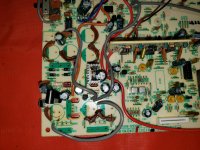
About 2 months ago I removed this working unit from my main system. A couple weeks ago I was scavenging a transformer from a CDC-3A and noticed bad glue corrosion on the power supply caps. So I decided to open the CDC-4A and sure enough the glue corrosion was starting. I decided to be proactive and remove the glue and replace any caps affected. I replaced the main power supply caps on the the main board with HW series Nichicon and all the caps on the separated analog process board with OEM capacitance. I have a fair amount of experience soldering and desoldering and have Hakko tools for both and haven't had this happen before.
After the recap at first power on I noticed a click sound from the laser assembly and it turned out to be the lens retracting and staying there. I powered off the unit removed the ribbon cable from the connector, anti stat solder in place, and measured voltages. Pin 17 focus coil on the connector is measuring -10.78V and 0 on 16 should be 0 on both I believe. I traced this to pin 1 and 2 of U106 (TA8410K). At this point I'm not sure and need some help tracking down the problem. I did try a different 8410 and no difference. I have a donor 4A if other parts are needed.
Power supplies and voltage regs seem to check out.
TA8410K voltages:
1= -10.78V
2= -10.78V
3= 0
4= -178.8mV
5= -12.14V
6= 10.2mV
7= 10.7mV
8= 0
9= 20.7mV
10= 11.9V
I have triple checked for cap polarity and shorts and cannot find anything and have even removed the analog process board.
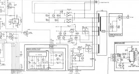
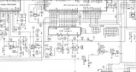
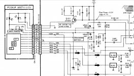
I have a schematic of the unit and have included the circuits.
I didn't replace the multitude of 47uf caps but did measure some and according to my cheap checker they have around 2% V loss but normal capacitance.
This player uses the TDA1541A S1 in simultaneous mode and sounded very nice and was very expensive new. I would really like to try and keep it alive.
Laser assembly is: PWY1009 / PWY1010
Thank you for your help!
Mark K.
History:
About 2 months ago I removed this working unit from my main system. A couple weeks ago I was scavenging a transformer from a CDC-3A and noticed bad glue corrosion on the power supply caps. So I decided to open the CDC-4A and sure enough the glue corrosion was starting. I decided to be proactive and remove the glue and replace any caps affected. I replaced the main power supply caps on the the main board with HW series Nichicon and all the caps on the separated analog process board with OEM capacitance. I have a fair amount of experience soldering and desoldering and have Hakko tools for both and haven't had this happen before.
After the recap at first power on I noticed a click sound from the laser assembly and it turned out to be the lens retracting and staying there. I powered off the unit removed the ribbon cable from the connector, anti stat solder in place, and measured voltages. Pin 17 focus coil on the connector is measuring -10.78V and 0 on 16 should be 0 on both I believe. I traced this to pin 1 and 2 of U106 (TA8410K). At this point I'm not sure and need some help tracking down the problem. I did try a different 8410 and no difference. I have a donor 4A if other parts are needed.
Power supplies and voltage regs seem to check out.
TA8410K voltages:
1= -10.78V
2= -10.78V
3= 0
4= -178.8mV
5= -12.14V
6= 10.2mV
7= 10.7mV
8= 0
9= 20.7mV
10= 11.9V
I have triple checked for cap polarity and shorts and cannot find anything and have even removed the analog process board.
I have a schematic of the unit and have included the circuits.
I didn't replace the multitude of 47uf caps but did measure some and according to my cheap checker they have around 2% V loss but normal capacitance.
This player uses the TDA1541A S1 in simultaneous mode and sounded very nice and was very expensive new. I would really like to try and keep it alive.
Laser assembly is: PWY1009 / PWY1010
Thank you for your help!
Mark K.
Attachments


Last edited:
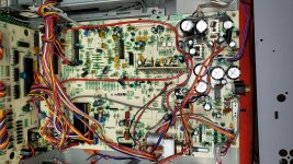
I see you cut the wiring harness. Are they all back as they were?
G²
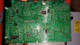
Hi, the first picture is of a CDC-3A parts unit which led to the discovery of the corrosion on the 4A.
Thanks,
Mark K.
reach out to anatech. i beleive he has substantial Nak repair experience.
good luck!
mlloyd1
Maybe he will see this and chime in! 🙂
Thanks,
Mark K.
All lines are back as they were and I left headers together on the 4A when they were desoldered/resoldered.
Mark K.
Mark K.
Hi,
Anyone have any ideas or are these players too complex to troubleshoot?
If I killed it someone can tell me and I won't mind and I won't pursue it further.
I feel bad if I somehow ruined it trying to be proactive but if it is destined for the recycle pile so be it and life goes on.
It's a good mystery anyway and maybe it'll get solved some day!
Thanks,
Mark K.
I'd wait for Anatech to chime in before making any decisions.
Have you forgotten to solder something like a ground connection?
I would recommend carefully rechecking your work for mistakes or damage to traces.
Have you forgotten to solder something like a ground connection?
I would recommend carefully rechecking your work for mistakes or damage to traces.
Thanks Kevinkr,
I have looked and can't find anything and I will look some more. I didn't do all that much that is why I'm a little surprised that this happened. Maybe in rush from new large filter caps? I have checked a few smaller caps out of circuit and individually they don't seem bad but maybe a combined effort and too much leakage? I honestly don't know and I'd rather not do too much more in case things get worse! Again not the end of the world if it's dead, but I am certainly patient to determine what failed with some guidance.
In the mean time I completely recapped a troubled NEC CD-730 which now is working perfectly so I'm not lacking quality CD play back.🙂
Mark K.
Hi Mark,
From your description of what was done, it shouldn't have happened. So, something must have happened that you aren't aware of.
Is it possible that the flex cable to the head cracked a few traces? That would sent the affected servo way off and peg that servo. You can try to plug the head from the CDC-3 into that connector on the main PCB and see if that head does the same thing.
Good luck on this!
-Chris
Hi Chris,
Thank you for the reply! The first thing I did upon lens retraction discovery was power off the unit, apply the solder blob, and remove cable from connection header.
Powering back on I measured pin 16 and 17 on the cable connection header, which control the focus coil. Pin 17 measured -10V coming from Pin 1 and 2 of U106. I then replaced U106 since that seemed easy and no difference.
I would rather not plug any laser assemblies back into a header outputting -10V where it shouldn't.
Not sure what to check next and I didn't and still don't, with a jewelers loop, see any shorts. Analog process board which I worked on a lot more is out the unit for testing purposes and no difference in operation fault.
Thanks,
Mark K.
Last edited:
It would appear according to the manual that Pin 4 on U106 should be 0V and I am getting some -mV there. I thought maybe I would lift legs 3 and 4 on U106 and then check output on 1 and 2 unless there would be some issue in this operation.
Mark K.
Mark K.
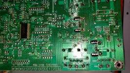
The second picture posted above shows what all was removed initially from the CDC-4A. I was no where else on that board. It is a relatively small area to look and nothing out of the ordinary. Everything went back in according to before pictures.
I have since expanded my search and found what looked like cold solder joints in a couple places which I touched up; all this after initial fault and no change.
Mark K.
I have since expanded my search and found what looked like cold solder joints in a couple places which I touched up; all this after initial fault and no change.
Mark K.
Hi Mark,
The photo diode amplifiers will generate an huge offset if they lose connection with the diode(s) in the pickup. That will generate your DC offset. You won't hurt the head unless you leave it on with the big offset. The only other things it could be is death by static, or you have a solder bridge you haven't found yet. I am including the flexible PCB in as you had to move it, and it may have been damaged because of you moving it.
So, just for chuckles and grins, stick the other head into that circuit. It doesn't need to be installed, you only need to plug the flexible PC board in. If it goes "click" to one side, the fault is somewhere else and you should turn the power off to avoid cooking those coils.
-Chris
Thanks Chris,
Should I remove the Anti Static solder blob on the flex PCB of the test assembly after insertion and before power on or leave in place during turn on to quickly test the Focus Coil?
To be clear the Flat cable has never been disconnected without first applying the solder blob which I thought was to protect the Diodes from damage.
I will carefully inspect the ribbon for cracks but I was careful to tuck it into the mechanism and not disturb it. While the work was performed.
If there is a short I'm having a hell of a time finding it.
Thank you again,
Mark K.
Last edited:
Hi Mark,
You could remove the short for the test. It will just place the system in a normal mode of operation and the goal is to control the unknowns if you can.
I read what you had done carefully, and what you are describing can't happen. Not unless something else occurred that you didn't notice. Now, I have assumed that you did check to make certain your supplies are all up. Measure them at some points beyond the fuses to also check those at the same time.
So, the question then becomes, what might have happened that you aren't aware of? Well, unintentional short circuits are number one. A cracked flexible PCB is another, followed by open solder connections. I'll assume also that you are a careful worker and you don't often make errors. But, when something like this happens, you should assume that you did in fact do something wrong, or maybe a new part is defective. Either one would normally not fall under suspicion, but that is because you are checking your own work.
Therefore it is helpful to approach this as if it came in from another technician. Put it aside tonight. Tomorrow morning, assume someone else did the work and start at the most simple causes and work up from there. It can be helpful to keep a list of direct observations only. No conclusions allowed of any kind! Once you are done with basic checks and tests, look at that list and draw conclusions from what you have written only. Doing this will guide you to the solution in spite of yourself.
The most difficult errors to find are your own. That's why a second set of eyes can be so valuable.
Best, Chris
I did test another assembly and same result. I had checked the entire connection header after the fault had been observed and the cable removed and everything else seemed correct.
I will wait till tomorrow and start taking voltages at various points on the Schematic and writing them down.
I figured since there was Voltage at pins 1 and 2 of U106 and according to the Schema there should be 0V that would have been the clue to point us in the right direction but I am not very experienced here. I assumed maybe it was a transistor or capacitor but that doesn't seem to be the case if you are only concerned with the Laser Diodes which definitely points to scrap heap destiny. I am quite careful but am also quite capable of mistakes! I do observe antistatic precautions and work on an antistatic mat; also I am not a technician but a struggling diy'er.
I am not seeing any fuses either. Maybe they are fuse resistors and not well labeled.
I'll wait till tomorrow for some fresh observance.
Thanks,
Mark K.
Last edited:
Hi,
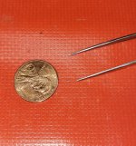
Maybe partial mystery solved! I found a small solder speck under the main board in the chassis. I'm guessing this is the culprit of what ever has happened. I am sorry I didn't catch this earlier and hope I haven't wasted too much of anybodies time. Picture below. Maybe spatter from my desoldering gun. Had to have been stuck somewhere bad and fell off with board manipulation after damage. I don't really know, I'm sort of grasping at straws here, and I've let a couple curse words fly since.
I took measurements which may or not matter at this point.
I have not discovered fuses after the power transformer or any discolored resistors.
Power Supplies:
U805 output pin = 5V
U806 output pin = -4.94V
U807 output pin = 8.02V
U808 output pin = 7.9V
R802 = one leg 11.85V to 11.80V other leg
R803 = one leg -12.2V to -12.15 other leg
Focus Coil circuitry:
R164 = one leg -179.3mV to -181.3mV other leg
R165 = one leg -1.2mV to -181.3mV other leg
R131 = one leg -34.8mV to -48.8mV other leg
C156 = one leg -4.94V to .1mV other leg
VR104 = center leg -71.3mV
TP 5 = -6.1mV
TP 6 = -48.8mV
Laser assembly cable Header CN-101 cable removed
Pin 1 = -1.4mV
Pin 2 = -1.7mV
Pin 3 = 0
Pin 4 = 0
Pin 5 = -.3mV
Pin 6 = 4.99V
Pin 7 = .1mV
Pin 8 = -4.94V
Pin 9 = -1.3mV
Pin 10 = -4.94V
Pin 11 = -.5mV
Pin 12 = 149.5mV slowly climbing looks like this should be 0V from Q101
Pin 13 = .1mV
Pin 14 = 20.5mV
Pin 15 = 0
Pin 16 = 0
Pin 17 = -10.86V
Thanks again and extremely appreciative for any and all help,
Mark K.
PS: I think I have bruised my rear end from kicking myself.😡
Attachments
Hi Mark,
That speck is a little small to be problematic unless it was between the pins of a surface mount IC. What is the actual current status of the CD player?
Normally we don't take a whole bunch of voltage measurements. Just the ones in the circuit we are having problems with.
If you look at the laser head part of the schematic in the box labeled "PICKUP AS S'Y (1/2)"? The diodes that matter to the focus servo are the squares marked A through D. The E and F diodes are for tracking (E-F balance) and tracking offset adjustments. The E-F balance is a critical adjustment, so do not touch that one. VR1 on the pickup is marked "LASER POWER". Never, ever touch this on any CD Player! You can very easily burn out the laser diode, really easy in fact. "LD" is the laser diode and "PD" is the monitor diode used to control the laser power through adjusting the laser current. If that becomes disconnected, bye, bye laser diode. Instantly.
So now you can understand the laser head a little better. The short on the flexible PCB that you solder and desolder goes across the laser diode. The head is well protected when this is shorted.
Fuses. If you put up a section of the power supply regulators, you can see symbols indicating fuses. In many products of this era, these fuses are called semiconductor fuses by some. They look exactly like a TO-92 transistor, but with two legs. There is another case for these as well. Again, they look identical to a type of transistor, and again they only have two legs. This type is a small black rectangle with a small curved section near one end (to mark the emitter end in the transistor that uses this case style. The first ones I encountered took me a little bit to find them. After that I ordered a ton of them just to have the little stinkers. The case style doesn't matter, they are interchangeable. The other type of current interruption device is a special resistor. They open when they reach a certain temperature, but they do not burn. So what that means is you may be looking at one and never know it is open. The most common resistances are 2R2, 3R3, 4R7, 5R6, 6R8, 7R5, 8R2, 9R1 and 10R0. These you have to measure with your meter as well. Remember, visually they most often look just fine.
Hopefully this helps you troubleshoot more easily. If you can, scan the section where the pickup diodes go into the chip and the focus servo and output. I'll help you through how it works.
-Chris
- Home
- Source & Line
- Digital Source
- Nakamichi CDC-4A Laser Focus Coil -10V after new power supply Caps