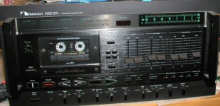
I'm having some problems with my cassette deck and I was wondering if it's something that I can fix or if it's out of reach without the right equipment.
When I go into the auto calibration mode the auto azimuth alignment unit seems to run out of its limits and starts to click.
From what I can see, the the auto azimuth alignment unit has its own motor to swing the "pendulum" through its range until it senses perfect azimuth.
I can only guess that the motor is capable of reversing? It seems as though my unit is wanting to go in only one direction until it runs out of its limits.
Anyone willing to take a stab at it?
I'd appreciate any help. I was told if I decide to send it in for repair, I was to ship it to Electronics Service Labs.
Thanks
John
As you can see, it is sitting far left of center:
An externally hosted image should be here but it was not working when we last tested it.
Well, a second try ...
I`ve written a long explanation of how the azimuth adjustment system works but somehow I`ve lost it. So a short version now.
I think the failure is in the auto azimuth motor driver. This is a bidirectional motor and it needs (+) for the one direction and (+) for the other. The driver decides this reading the potentiometer which is in the black box to know where the position is and also it takes signals from the phase comparator. This is a loop which stops when the azimuth is correct and there is now phase difference. So, there are 2 matched, complimentary transistors there. 2SD471 and 2SB564, I think the originals that Nakamichi used are from NEC. One of them is bad. Check them and replace them if required. These 2 are a bit hard to find but not impossible.
By the way the Dragon has them also for its NAAC. So, this is a 50 Cent job, do this. Good luck. Best regards ...
netwalker,
Since you seem to be well expierienced with NAACs, maybe you could advise me on my machine.
Whenever Play is pressed (in record mode including) the meter display are always at max without regards for pot or input settings. They go off only in stanby (Stop).
Since you seem to be well expierienced with NAACs, maybe you could advise me on my machine.
Whenever Play is pressed (in record mode including) the meter display are always at max without regards for pot or input settings. They go off only in stanby (Stop).
Attachments
Well, the Nakamichi 1000ZXL is a very complex machine. It is hard to say where the problem really is. I have a service manual only for the 1000ZXL Limited Edition which doesn`t contain any adjustment procedures. If I were you I, would start with the adjustment procedures first. May be you are lucky and your deck is just out of tunung and you don`t need further to troubleshoot. Generally spoken the level meter consists of two chips which control the beginning and the end part of the LED display. The 1000ZXL Limited has two TC4022BP from Toshiba, The Dragon has two (TC5081P also from Toshiba). The 1000ZXL Limited has 2 boards which control the LED display. FL Indicator P.C.B. "A" and FL Indicator P.C.B. "B". The two chips are on the "B" board, on the "A" board there is a pot to take an adjustment. Generally there is an adjustment procedure for the LED display. May be if I take a look at your service manual I can tell you whether and if there to adjust. Iif you can not adjust this then you have to make a little troubleshooting. Indeed, the 1000ZXL is a very complex mashine and you have a very nice one as I see. Service manual is a must. The troubleshooting if required then includes checking the input voltages, signals, and may be some components. Perhaps it is also important to know when and how all this with the LED display began.
Best regards ...
Best regards ...
To Lbow 🙂 Sorry, I was too fast with the keyboard ...
The azimuth motor needs (+), positive voltage for the one direction and (-) negative voltage for the other direction ... 🙂
The azimuth motor needs (+), positive voltage for the one direction and (-) negative voltage for the other direction ... 🙂
netwalker said:Perhaps it is also important to know when and how all this with the LED display began.
Thanks for advice.
The unit worked fine originally, then I put it to rest for 3 years; when I first switched it on after that period, something blew in a PS and I had to replace one transistor (in PS). That brought the unit back to normal operation again, except for a meter, which always stays at maximum, whenever inb play mode.
I have service manual with adjusting procedure/troubleshooting guide, but I don't recall it says anything about that type of behaviour. The unit is indeed very complex, and I was postponing that repair for more than a year now.
Hi again,
Hm ... this makes the things somewhat different. Again, I`m looking at a 1000ZXL Limited Edition Service Manual and shematic may differ somewhat ... Nevertheless i would think a little bit in order to help you.
Well, it seems that when something blew in the power supply not only this transistor was blown but also some other part. You`ll have to make a check.
As I told you in the previous mail, the led display consists of two boards. The second one "FL Indicator P.C.B. B" is directly connected to the "Power Supply P.C.B"through the connector "CN-37" wich has 5 pins:
1. AC
2. AC
3. GND
4. -39V
5. +5V
Pin 1. and 2. (AC) are going directly to the "Fuse P.C.B." and are fused with F404 and F405 (both are 1A 250V). So, check these two fuses first. Be aware of the safety precautions. If the fuses are blown replace them only with the specified ones.
So Pin 3. is ground, check that too and also check the voltages of Pin 4. and 5.
If the fuses are ok, chesk the voltages at these pins and the ground. If the voltages and the ground are ok and the display is still weird, the problem is somewhere on the one of the both display boards. Or on both. Then you will have to check the voltages on the boards. Do this and then we should know more.
Good luck. And don`t forget ... Safety first. 🙂
Best regards,
Plamen
Hi,
The fuses are fine and voltages check out fine too. AC between pin 1 & 2 is 5.2V , pin 4 has slighty lower voltage ( -37.7V).
The fuses are fine and voltages check out fine too. AC between pin 1 & 2 is 5.2V , pin 4 has slighty lower voltage ( -37.7V).
Well, the problem is tricky. Please tell me wich transistor exactly was blown, its type and tell me with what type did you replace it ... What else did you do to the deck? Putting apart, cleaning, adjustments. It is important also to know if this is the only malfunction you have. Did you check every other function and found to be ok? Before we go further on check these things first:
1. By the way, I had the same effect on my dragon ... I dismantled it in order to clean it and to replace some parts. On putting it together i have either forgotten to put a ribbon cable on its place or i swapped 2 of them. The flat ribbon cables have small paper etikettes saying in which connector on the board the cable goes in. They fall easilly off and you can do a failure. So if you took the deck apart for cleaning ot adjustments or to change a part verify this even if it sounds a little funny.
2. If the deck was on a shelter for three years or so and after this you made it on and something blew, then maybe there was dust in it, moisture, or something fell in. I would make aditional visual inspection verifying that nothing is shorted. Accumulated dust may be conductive. If there is a dust or some other garbadge dust it off using a can of compressed air. As far as I know the deck has also a battery to support the memory of the computer of the deck. Is it good ? If you leave a battery for a long time it gets bad and acid comes out making a small (or a big) mess on a board. So check that too.
3. Did you check your ground as well, not only the voltages ?
Check for contact between ground pins and chassis. What about the other voltages on the two LED boards, not only the pins you`ve told me about check where you can.
4. Changing electrical parts means that you have to make an electrical adjustment. Because the new part or a replacement one has different characteristics. So, there must be an adjustment procedure for the level of the LED display. On the dragon you play a signal, 0db and adjust the level meter to this level. There are also reference voltages. Check in your service manual if there is such a procedure and check if the LED display reacts at all to this adjustment. Perhaps the LED display is ok but it is too sensitive and the movement is beyond the scope of it. Check for reaction using the LED adjustment procedure. On the first LED PCB there is a tweaker VR601 tell me what it is used for. I think this is a gain or clock adjustment, if you find the procedure for this try it. See if the LED display reacts.
5. Check also the voltages on the LED boards. The shematic says where and what voltage is to be checked.
6. After all the first LED board takes the stereo signals to display them ... check if the signal is comming in as it should come. This way you would know if the LED is functioning correctly and the incoming signal is wrong or the signal is ok and the LED is wrong.
7. Check for Q209, Q109 on the second board. There goes the stereo signal first through.
Generally I think of three possibilities:
1. Something is shorted somewhere
2. Something is blown
3. Out of alignment. Too much gain or adjusted too sensible. (most likely)
Well that are my suggestions for now. It is a little hard to find the problem this way but I think we should cope with it. At least I would`t give it up that easy.
I`m staying tuned to know what`s going on.
Best regards,
Plamen
Peter,
Your problem is bad relay contacts. Clean the card connectors whle you are in there. Use the gas filled relays for replacement if you can find them.
-Chris
Your problem is bad relay contacts. Clean the card connectors whle you are in there. Use the gas filled relays for replacement if you can find them.
-Chris
Lbow,
You may have worn capstan bearings. Also, the plastic / nylon part may need replacing. Belt tension is important as well.
To check, use a cut away cassette to view the tape path. If the tape travels toward the mechanism, the bearings are worn. Simple.
-Chris
You may have worn capstan bearings. Also, the plastic / nylon part may need replacing. Belt tension is important as well.
To check, use a cut away cassette to view the tape path. If the tape travels toward the mechanism, the bearings are worn. Simple.
-Chris
Thanks!
It's been a while, but thanks for your help with my problem. I took my cassette deck to my local repair shop before any answers were posted to this forum.
They found one plastic gear that adjusts the tape head to be broken. I'm not sure if this contributed to the auto azimuth alignment problem.
Next they found the push button that is depressed to start the auto calibration mode to be sticking. Again, it's not sure if this caused the run on with the auto azimuth either.
The repair inspection stopped at that point because even though they were a Nakamichi repair shop they didn't have the service manual, the alignment tapes or any parts to fix the gear problem!!!
I spoke with Stephen Sank of Albuquerque NM. His shop has the alignment tapes, the parts, the service manual, and quite a bit of experience when it comes to this machine. I'll print this thread and enclose it with the package I'm sending him.
I'll come back to this thread to report what the actual cause of the problem was with this machine and what was done to get it back up to snuff.
Thanks for all of your help,
John Kufrin, Raleigh, NC
Hi John,
I think you will find repairing this machine well worth it. Have Stephen calibrate it while he is at it. Send him a fresh blank of what you use.
This actually matters as a tech can cal this machine far closer than the autocal can. Besides, only the 1000ZXL cals each channel individually and runs through twice. Your Dragon therefore will benefit.
-Chris
Stephen Sank is a crook!
I created this post over two years ago. By recommendation, I shipped the cassette deck to Stephen Sank.
I paid Him $350 to repair the cassette, which he said he would repair the malfunction, upgrade the caps, and have it back to me in a month.
After the first year of excuses and endless voicemails, he stopped returning my calls.
I continued to e-mail and call for another year.
Finally, I called a private investigator located 2 blocks from his business.
The PI was able to recover my Nakamichi 1000ZXL from Stephen Sank. The PI was handed the deck with none of my original packaging, the faceplate was detached from the chassis and the glass bezel was missing. Just handed it to him over the counter.
I paid the PI to take the pieces to a pack-and-ship to have the cassette deck returned to me.
Over two years and to get my stuff back like this.
I am going to see him before I die.
John Kufrin
Actually, I was more concerned about the Naka..😀
(and I'm happy with the less complex CasetteDeck 1)
Arne K
(and I'm happy with the less complex CasetteDeck 1)
Arne K
Hi John,
I am deeply sorry to hear that this is what happened. I've rebuilt several of these machines in my time, but no longer have the manual, tapes and jigs, or the uP calibration set (controls the micro so you can calibrate it).
He took money from you before he did the job???! Danger! Danger Will Robinson!
You ought to take him to court for this. You should also contact Nakamichi and let them know what happened. If he is still authorized warranty, they will make this very unpleasant for him.
Wow.
-Chris
The broken nylon screw must be replaced.
Then the azimuth motor gear must be turnde by hand apx in the middle .
Now adjust the nylon screw by eye apx. to the middle and try the calibration .
Maybe you have luck .
I have the complete manual of the 1000 ZXL .
Its very complex and without the required tools your chance is small .
I have also a complete new mechanic unit incl. heads on stock , also few other parts for the ZXL , but im located far away ...
- Status
- Not open for further replies.
- Home
- Source & Line
- Analogue Source
- Nakamichi 1000ZXL Problems