It'll be the distortion spectrum again. Feedback tends to reduce low harmonics while increasing the level of high harmonics due to IMD (the output harmonics interact with the input as they both pass through the gain stage, and that can disguise itself as noise that is only present together with a signal). That's just the nature of the beast.
All Naim circuits rely on loop nfb. Distortion is average and obviously rising with frequency. Again, part of the brand's sound.
Valve aficionados love the warm, thick sound of the 2nd harmonic distortion!😉
Yup. Some even insist the second is stronger than the first 😛
You jest, but THD is notorious for giving bad sound a pass, when an objectively more useful metric (with no side gig in selling 80's ghettoblasters) would at least weigh the harmonics with a Fletcher-Munsen like window to make sure the screechy 4kHz range gets more attention.
It was just an experiment with what I had to hand to see if the microphonics could be damped, never intended to be used.A drop tantalum capacitor covered in blu-tak - that's pretty much a guaranteed incendiary device if the tantalum fails isn't it?! FR4 is only flame retardant, it will eventually burn.
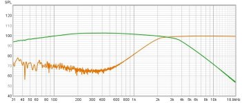
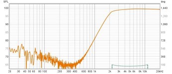
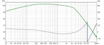
Took some measurements with REW.
There is a noticeable drop in the LF - 6db down at 40Hz which is a surprise. Might this be due to capacitors being out of spec?
The distortion measurements are also poor - might be the 30year old Tantalum coupling capacitors? I'm thinking about replacing them with Nichicon Muse or Elna Cerafine polarised caps.
Crossover frequency is correct ~ 2.5k.
Attachments
Where does this myth come from? Negative feedback reduces all output harmonics, so long as you have a decent amount of open loop gain in the first place. This is a simple mathematical truth. So unless your open loop gain drops too low before 20kHz you will never see audible harmonics or intermodulation products increase when applying negative feedback.It'll be the distortion spectrum again. Feedback tends to reduce low harmonics while increasing the level of high harmonics due to IMD (the output harmonics interact with the input as they both pass through the gain stage, and that can disguise itself as noise that is only present together with a signal). That's just the nature of the beast.
By the way negative feedback will typically increase the distortion going into the output stage - but precisely in a way that reduces the distortion on the output of that stage - that is the true nature of the beast, it does whatever is needed to linearize the output.
But I guess sometimes people apply negative feedback when there isn't enough open-loop gain, which would explain how this myth arises - open loop gain is the fuel necessary for feedback to do its magic. That's why the top performing audio opamps have gains of 10 million or more, and why the VAS in a power amp is one of the most critical parts for THD maximization as it provides most of the gain.
The confusion is due to the reference point.
Applying negative feedback around a non-linear function creates harmonics that may not have been present in the non-linear function alone.
For example, in a square-law device, applying feedback causes the third and higher harmonics to appear. The magnitude is small and drops very rapidly with increased feedback.
Ed
From doing lots of simulations and looking carefully at the individual distortion components. 0.1% THD vs 0.01% THD (at equal output voltage) tells me almost nothing if there's no additional insight accompanying it about the tonal character of the distortion.Where does this myth come from?
I've found that a modular software synthesizer with an old-school additive synth can be a great way to get a feel for the sound of various harmonic patterns. I know from empirical tests that shaping the distortion for minimal high harmonics, at the cost of 'mediocre' H2+ H3 is an audibly correct approach.
As said before, Naim choses (all) components, and even shakes their cables on a special machine, to match their unique sonic signature. If you don't agree with that then just buy some other kit?

No such device in reality I assert: all discrete semiconductor devices produce a spectrum of harmonics, generally feedback will reduce all of these, certainly if there's a healthy amount of open loop gain to use it will knock them all down a lot.The confusion is due to the reference point.
Applying negative feedback around a non-linear function creates harmonics that may not have been present in the non-linear function alone.
For example, in a square-law device, applying feedback causes the third and higher harmonics to appear. The magnitude is small and drops very rapidly with increased feedback.
Ed
By the way if you use a pure square law device as an amplifier without feedback, you are not making an amplifier, you are making a mixer (in the RF sense) - the output would never be negative(!). In practice you'd degenerate (local negative feedback) in order to have a sensible starting point for amplification for something like a FET, so the law is more like a + b*(x+c)^2, ie constant, linear and quadratic terms, with the quadratic term being the smallest as you arrange |x| < c
Consider a FET with a roughly square law response, plus added degeneration (so the 2nd harmonic is significantly less than the fundamental). Measure it and you'll see 3rd, 4th etc harmonics too, descending in amplitude with higher order. Real FET devices do not accurately obey the simplified models of FETs. (You have to beware of over-simple simulation models here, they can really lead you astray!).
Apply even a modest amount of negative feedback around this FET and all these harmonics can usually be reduced, even if some of them will be picking up energy from lower harmonics, the feedback is pushing them all down anyway... Usually everything improves with more feedback in most real life situations. Once you've applied a large amount of feedback there is no issue, all distortions are way way less than originally.
So yes in theory you can have individual harmonics increase a bit as feedback level is increased, but its an outlying curiousity and of little relevance to any pragmatic circuit design I reckon. Certainly local negative feedback such as source-degeneration and emitter-degeneration is routinely added without care or thought to this possilibiity, often its tweaked experimentally as local feedback can detract from global feedback, so there's often a happy point where the local feedback gives the global feedback a good starting point of linearity without robbing too much open-loop gain.
The key insight of negative feedback is that a loop allows the reciprocal of the transfer function of a resistive divider (ie a very very accurate gain factor) to be transfered onto an active amplifier - the more open loop gain available to turn into feedback, the closer the amplifier approaches the reciprocal of the divider. Until issues of stability start to get in the way, of course. A / (1+AB) --> 1/B as A --> infinity
Mark - My shortwave radio uses a JFET for the RF amplifier because JFETs produce fewer intermodulation products than bipolar transistors. The mixers also use JFETs because the desired output (frequency difference) is readily created by the square-law.
These JFETs have only DC bias.
Ed
These JFETs have only DC bias.
Ed
Your right low distortion does not equate to good sound. Look at tube se amps.10% distortion at full rated power. Glorious sound. Mmmm audio is full of conundrums.
Early bass roll off can sometimes be heard as fast bass. Depends what the group delay doesThere is a noticeable drop in the LF - 6db down at 40Hz which is a surprise. Might this be due to capacitors being out of spec?
Bought old Naim Nait 3 with NEC blue tants and Samha caps in signal path. I'm not touching it! I had dozen of much better amps but none gave me so much pleasure in listening to bedroom setup and I love the look of it sitting on top of CDX player . I immediately bought 50 tants ...🙂
A higher 3dB point actually increases the group delay near the cut off, but can lift you safely clear of the much greater group delay from a ported speaker.@davidsrsb
I find what you said interesting, could you elaborate please?
See https://trueaudio.com/basslst2.htm
- Home
- Source & Line
- Analog Line Level
- NAIM use Tantalums for coupling caps in their IXO Active Crossover - good or bad?