Hello ! The gain can be changed in R6 and R16 values (according to the Jim Salabim scheme).......
I think "R16" should be "R19"?
I specified R16 according to the Jim Salabim scheme at the beginning of the topic .
Attachments
Last edited:
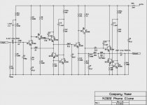
When using BC 550/560 transistors, the circuit will generate . You need to add capacitors C9 and C10 - as shown in the photo .
Please explain why! Thanks 🙂
Hello !Hello Tell me how to adjust low and high frequencies in the diagram?
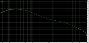
The frequency correction complies with the RIAA standard . And you don't need to configure anything there . Here is the measurement of the NA-322 board -
Attachments
Because the BC550 /560 are different from the original ZTX transistors . Without correction capacitors, there can be high frequency generation in the circuit . I had it like that .Please explain why! Thanks 🙂
Hello vsmusic,
sorry to reactivate this old thread. Could you please tell me (us) the new values of R6 and R16 (refering to Jim Salabim scheme) to got a gain of 40dB, which will be +5dB w.r.t the original 322 board if I‘m correct.
Thanks and Best Regards
Phonoton
sorry to reactivate this old thread. Could you please tell me (us) the new values of R6 and R16 (refering to Jim Salabim scheme) to got a gain of 40dB, which will be +5dB w.r.t the original 322 board if I‘m correct.
Thanks and Best Regards
Phonoton
Hello Phonoton - In my instance of this preamp, these values are set. The changes are shown in red .
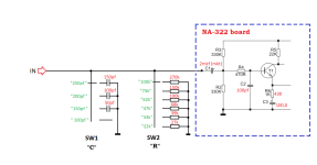
The second photo shows the circuit of the switches for adjusting the input resistance and capacitance.
The second photo shows the circuit of the switches for adjusting the input resistance and capacitance.
Attachments
Last edited:
Hello vsmusic,
many thanks for providing the schematics 👍 Two questions left… How you determine the new values of R6/C3 and R16/C5? By simulation or you are able to calculate it? The function of C3 and C5 is not really clear to me since I know CE only in parallel to RE. Furthermore you added 20pF on T3 (base) and 6.8pF on T8 (base). Is this to prevent oscillating of the circuit due to increased gain?
Thanks and Best Regards
Phonoton
Phonoton - Capacitors 20pf and 6.8pf may be needed if high-frequency generation appears in the circuit . My copy had that. Perhaps because of the BC550C/560C transistors. I have not tested with other transistors.
Capacitors C3 and C5 affect the lowest frequencies ( about 20 Hertz ). I have already published here a graph of the frequency response of this preamp - with ratings of C3 and C5 of 100uf each.
Capacitors C3 and C5 affect the lowest frequencies ( about 20 Hertz ). I have already published here a graph of the frequency response of this preamp - with ratings of C3 and C5 of 100uf each.
I checked the values of R6 and R16 using measurements (oscillator / oscilloscope / RMAA program.)
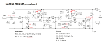
Hi! I have traced the Naim NA322/4 MM phono board PCB layout from some photos that I found online. I didn’t find any schematic, but there were enough pictures and some descriptions so that I could identify the parts.
Anyway I have some questions left:
1. Can anybody tell me if I have identified the transistors correctly? I am not absolutely sure which of the 10 transistors are ZTX384 and which are ZTX214.
It was hard to tell this from the pictures. Unfortunately I don’t understand the circuit enough and don’t have enough background knowledge to really be able to figure this out logically.
2. Is the polarity of the tantalum caps correct?
3. I can use BC560 instead of ZTX214 and BC550 instead of ZTX384, right?
4. Do the transistors have to be matched? And which have to be matched?
Thanks so much in advance!
Why not simply buy a pair of Ryan Sound Labs boards?
RSL boards are not available anymore but for aftermarket I prefer NJ boards anyway. Also good to know how gain can be changed on the NJ boards since circuit is almost the same as on NA322 boards.
Does anybody know if an NAIM Stageline (N) use the same circuit and which gain is applied?
Does anybody know if an NAIM Stageline (N) use the same circuit and which gain is applied?
- Home
- Source & Line
- Analogue Source
- NAIM NA322 MM phono board