Hello all, so I had the output on the T751 drop to nearly nothing. There was a previous issue and I replaced the surround board. Everything worked fine since then.
I just decided to try and fix the new issue and am stuck.
I re-capped the entire front amp board.
I pulled each of the main transistors at the bottom and they all seemed to test OK off board.
I seem to be getting proper voltage at the opamp on the load board, and proper voltage out to the front amp board. If I turn the volume up very high, I can hear the source a bit, but it's very faint.
Problem persists through headphones.
Sound completely gone if I change listening mode to anything but stereo.
I'm not sure where I should be focusing my effort now. There are a bunch of smaller transistors on the board I didn't check yet as it would be pretty time consuming to take them all out of circuit.
Any direction would be appreciated
Attachments
Last edited:
Changing caps and pulling transistors is a difficult way of solving the problem because you cannot learn what state the circuit is in and what might actually be happening, and depends upon getting lucky. It could be in protect mode, or in the relay circuit, a bad solder joint, or even a power supply issue., so many possible areas outside of the main audio pathway.
I recommend that since you have a schematic, you will need to scope the signal and find out where you are losing it. If you can hear the output faintly with the volume up, you are getting audio most of the way. Oscilloscopes are really cheap now (my workhorse I got for under $30). Using a meter can be used to detect audio if you switch it to AC voltage if you have a low enough voltage scale.
Divide and conquer. Is the audio missing from all sources? From all outputs (including surround?) Check the signal coming from the main board to the front amplifier board. This will tell you if the problem is upstream or downstream - cuts the problem in half. Same with main board to surround board. Power supply is on the main board and power travels to other boards via the connectors- are all of the voltages present on both main board and other boards? You have a ton of documentation there, just takes time to track it down with the meter and scope. Print it out, make notes, and hang in there.
Thanks for the detailed reply. Yes, the relays are operating and it's not in protect mode.
I changed the caps because they were nearly all leaking and decided to check the transistors while I had it apart. I have a hard time checking the board while connected due to the shortness of the ribbon cable connecting the main board to front amp board. I might need to just get a bunch of jumper wires and connect it that way.
I did test voltage to the main transistors that I could reach. I suppose I was just hoping someone might have an idea what might cause those symptoms, but it's true it could be anything along the path, though it must be before the three front channels split and before it sends to the surround amp.
The main board goes to front and multi, and the signal goes to the secondary before going back to the multichannel as far as i can tell..
the power for the surround goes through the front amp board, and signal to surround goes through the multichannel board.
An oscilloscope was going to be my next purchase. I'm going to need one anyways. Working on a digital surround receiver is quite a bit different than the usual stereo amps due to the routings between many different boards.
I'll try what you said and go from the inputs to the output from the main board first.
Not sure if you'll see the update, but in doing as you said, I've narrowed it down to the multichannel board.Changing caps and pulling transistors is a difficult way of solving the problem because you cannot learn what state the circuit is in and what might actually be happening, and depends upon getting lucky. It could be in protect mode, or in the relay circuit, a bad solder joint, or even a power supply issue., so many possible areas outside of the main audio pathway.
I recommend that since you have a schematic, you will need to scope the signal and find out where you are losing it. If you can hear the output faintly with the volume up, you are getting audio most of the way. Oscilloscopes are really cheap now (my workhorse I got for under $30). Using a meter can be used to detect audio if you switch it to AC voltage if you have a low enough voltage scale.
Divide and conquer. Is the audio missing from all sources? From all outputs (including surround?) Check the signal coming from the main board to the front amplifier board. This will tell you if the problem is upstream or downstream - cuts the problem in half. Same with main board to surround board. Power supply is on the main board and power travels to other boards via the connectors- are all of the voltages present on both main board and other boards? You have a ton of documentation there, just takes time to track it down with the meter and scope. Print it out, make notes, and hang in there.
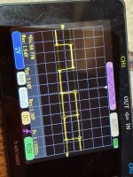
Just not sure what to expect from this IC, I'd just assume the readings in getting are showing an issue with the m62447sp IC...
I could be wrong, but i wouldn't think the waveform would flatten and drop in strength by a few divisions. Square wave is on input pin for front left and right, the flat form is output pins
Attachments

Check something for me- A really easy way to see if a stage is passing audio (on low voltage circuits only) is to use a fine point pick, held by your hand, to touch various signal points in the pathway. (Don't short between components or pins.) Your body acts like an antenna, picking up hum and injecting it into the circuit. Use the pick to touch the FR, FL, and C input signals to the front amp PCB, near R5134, R5135, and J541 or the connector pins. If the front amp is working correctly, you will hear a click or pop, and a loud hum or buzz from each speaker output as you touch it's input (Beware, it could be QUITE loud, so use very small disposable test speakers rather than your nice room speakers). If you get that for all channels, you know the front amp is working, and the problem is upstream. If it does not make this noise, you know it's the amp. You have done quite a lot to this amp, and should make sure it's still working properly.
Assuming the amp works, move upstream, injecting the signal at various places, and it will tell you where you are losing the signal.
The volume chip is digitally controlled through a serial interface. Your second picture clearly shows 1's and 0's of a digital serial connection, not an analog signal. If your front amplifier board is working according to the previous test, and you believe the problem is upstream, pick the outputs of this chip and make sure you get the buzz, and if you do, pick the inputs to the chip turning the volume control up and verify you get the signal out.
I will check with a pick later as you suggested. The volume is adjusted (albeit very very low) with the volume knob, and the only increase to normal volume as a brief one second burst when switching the unit off. I was injecting a 200+hz square wave signal and following it through the signal path. That IC was as far as it got. Before turning into that flat high frequency line you see in the picture.
I did notice an issue with the 35 pin ribbon cable from the keyboard to the secondary board as well, but I'm not sure how much of an issue that would cause with just stereo mode.
Will report what I find with the pick.
Thank you so much for the help so far.
I did notice an issue with the 35 pin ribbon cable from the keyboard to the secondary board as well, but I'm not sure how much of an issue that would cause with just stereo mode.
Will report what I find with the pick.
Thank you so much for the help so far.
The amplifier is working, and loud noise could be heard on those three channels.
No real sound on either end of that Volume chip though, maybe a barely audible tiny click on either side no matter what volume is at, max/min.
If I'm understanding correctly, this would control the volume of the signal, then go through the opamps before heading to the amplifier boards.? Shouldn't the signal I'm scoping at least maintain, if not increase when going through this IC?
I expect the volume control chip would not significantly amplify the signal, so if the volume were at maximum, the sensitivity to the buzz would be basically the same at both the inputs or outputs. I think you are losing signal through the op-amps and/or the tone controls. Again, divide and conquer:
The signal arrives at the front amplifier board through J603B. You have confirmed from this point downstream is working. These signals leave the multi-channel board on J603A. Make sure you get the same buzz here. (if not, it's the cable, but likely not.)
Then move upstream- the center channel does not pass through the tone controls, but comes from the output of the op-amp U606A pin 1. Buzz there? Then check the input of op-amp U606A at pin 3, or at the volume control chip output pin 33. Buzz there? If not, the op-amp or something in that area is a problem. Check both sides of C638 and C628.
Front L and Front R that feed the front amp are coming from the volume control chip, and passing through the tone/volume control circuitry, so starting at J603A work your way upstream- How about the output of the tone controls at R679 and R680. Buzz there? If so, work upstream- check the inputs of the the tone control op-amps, R683, R684, or at the outputs of the volume control, pins 31 and 32. You said you had no buzz there, but check both sides of C618 and C619 (3.3uF).
I'm seeing what is likely a lot of muting circuitry here too- It could be that as well. Center mute Q616 and Q601. Front mute Q614, Q611, and Q612. If we start suspecting a mute issue, don't pull the transistors, we'll figure out if it's muted by the voltages.
Update: I'm starting to wonder if the muting circuit you touched on might be in play.
As soon as I reconnect J603a to the front amp, the loud buzz is only a tiny click, with the right being slightly louder than the left. It's almost inaudible unless wearing my monitor headphones in a silent room, but it's there. I'm only getting at at the output of the volume chip though.
Present at r679 r680, q611, q612, c618, c619, u608, u605
The only proper buzz was from pin 5 of u608 in what I gather to be part of tone control circuit strangely enough.
Getting proper - and+ 12v to the board, but I didn't check voltages at that transistor which I'm guessing is q614.
I may be jumping ahead, but it's kinda tough to hear the click as it just "mutes" when connected to the circuit. I tried jumping the boards with different wires to the same effect.
Ok, sounds like the multi-channel board has mute turned on, and mutes the inputs to the front amplifier (no buzz) when J603 is plugged in.
Look at Q611 and Q612, which are the NPN mute transistors for the outputs of the tone board. The collectors (c) pins are tied to the signal. The emitters (e) are tied to ground. Turning these transistor on (taking the base (b) pin more positive than the grounded emitter since they are NPN) shorts the signal to ground, muting it. The transistor driving these two transistors is Q614, which is a PNP. When Q614 is off, the -12V pulls the bases of Q611 and Q612 negative, making sure they are off. So, to mute the audio, the Front Mute signal (pin 7 of J705B) is pulled high (probably to 12V, but could be 5V) so the emitter (e) of Q614 is pulled higher than the base and the transistor turns on (since it is a PNP), pulling the collector high, which turns on Q611 and Q612.
Now, Q614 is the funky dude shown below. We're interested in what is happening at the e pin. If it's a positive voltage, then Front Mute is on and that is why you are getting no sound through the tone control. So, check that voltage, and either side of R694. If that is positive, mute is on.
The center mute works exactly the same way. Center mute (pin 9 of J705B) when high, drives Q616 (e) high (same dude as below), driving Q616 (c) high, pulling up the base of Q601, turning it on, shorting the center channel audio signal to ground and muting it.
I'll check that, I kinda have one hand tied behind the back with any other channels as I'm currently in search of a new ffc cable for the ac3 board, but I'll press on with the FL and FR channels. In case I do find the mute is on, I'll be chasing the voltage back to the brain on the key board yes? I only see a few resistors, a diode from the 5.6v rail, and a capacitor on that line just briefly looking.
If it's the case that there is positive voltage, would I follow that back to the main IC on the key board or is there another direction I should look?
If it's the case that there is positive voltage, would I follow that back to the main IC on the key board or is there another direction I should look?
Yep- continue upstream. As a quick test, you could temporarily short across C683 and the front two channels would be unmuted, and you can see if those work with volume control then. You could do the same thing, shorting across C685 to temporarily unmute the center channel as well.
Unfortunately I have +4.5v all the way back to the key board.
Do you see anything else aside from the microcontroller that could be causing this? It seems to be the case across all mute lines, 4.4ish volts all positive.
Yes, shorting c683 bypassed the effects from q614.
Do you see anything else aside from the microcontroller that could be causing this? It seems to be the case across all mute lines, 4.4ish volts all positive.
Yes, shorting c683 bypassed the effects from q614.
So- with C683 bypassed, do you get audio all the way from input to speakers, and the volume control works too?
If above is true, it sounds like the microcontroller (U201) has decided to mute everything. If the rest of the microcontroller shows life, I doubt it's a bad chip, but likely a reason you might be able to see in the operator's manual. Maybe a protection mode? Something going on it's not happy about.
If above is true, it sounds like the microcontroller (U201) has decided to mute everything. If the rest of the microcontroller shows life, I doubt it's a bad chip, but likely a reason you might be able to see in the operator's manual. Maybe a protection mode? Something going on it's not happy about.

Did you start with the obvious:
Check that the unit is not muted accidently? Yes I know but it happens, a button on the remote is easily pressed....
Try a factory reset. I "fixed" no sound issues on quite a few AVR's simply by a factory reset. On some models it's a key combination, some offer a reset option in the menu. Otherwise disconnect all power, disconnect any backup battery and discharge any large cap or supercap you can find and leave it like that for a few hours.
I didn't check the volume actually as I couldn't grab onto one leg of that cap. Had to maneuver a jumper wire onto the solder side. I'll check it later for good measure.
Next step after that will be to see if any of the functions going to the AC3 board are causing issue because of that cable. Maybe reflow the chip.
It didn't look the greatest as there was flux built up on the pins, which, in turn collected other junk. I've had to reflow other components over the year to fix other issues.
The protect circuit automatically shuts the unit off and flashes led when tripped as I tested that.
If all else fails, it's only a learning project at this point anyways and I can always bypass the mutes or use the parts along with my other collection to build a stereo amp out of it.
Volume does work yes. I might jump all the ac3 wires later and probe the microcontroller with the scope and see what it looks like.So- with C683 bypassed, do you get audio all the way from input to speakers, and the volume control works too?
If above is true, it sounds like the microcontroller (U201) has decided to mute everything. If the rest of the microcontroller shows life, I doubt it's a bad chip, but likely a reason you might be able to see in the operator's manual. Maybe a protection mode? Something going on it's not happy about.
Thanks for the reply, I've tried all that to make sure.Did you start with the obvious:
Check that the unit is not muted accidently? Yes I know but it happens, a button on the remote is easily pressed....
Try a factory reset. I "fixed" no sound issues on quite a few AVR's simply by a factory reset. On some models it's a key combination, some offer a reset option in the menu. Otherwise disconnect all power, disconnect any backup battery and discharge any large cap or supercap you can find and leave it like that for a few hours.
Tripping protection initiates shutdown in these units and flashes the LED.
You can check firmware version, but I can't factory reset in any traditional method, but the entire amp was in separate components for the last year, and after cleaning the keyboard, I made sure it was drained before reconnecting anyway.
I also contacted lenbrook for firmware just in case I needed to write to a chip, eeprom or mc, but they don't have this, it's only a learning project despite my love for the amp and sound, so I'm not going to order new boards even though they are available and cheap surprisingly...Lenbrook is great for having enough spare parts in warehouse.
Eureka! So I was getting an intermittent data signal from the u105 reset pin / cs4926 reset jumper. I reflowed u105 on the ac3 board and it's back in business. Wparks i can't thank you enough for the help, It was a step above most of the help I get on forums. Hopefully later on I'll be able to give as sound advice as you gave me.
For anyone else fastidious enough, and as stubborn as I am to repair an "oldish" receiver you could buy on ebay for 60 bucks. There was also a loose ACv connector on the secondary pcb that was preventing the surround, center channels from coming on in surround mode. No visual indication for any of this even under magnification.
- Home
- Amplifiers
- Solid State
- NAD T751 low output issue