Problem child amp (henceforth PCA), has no serial number on it- but has series A boards and an early input board (without C115/C116)- it does not have "power envelope"- which I think correspond sot the later circuit.
Given the 2700 is effectively an evolution of the 2200- I think the -35 is the right voltage.
I have another early NAD (fully functional) which I will measure as well-it's serial is 5060XXX, so prior to power envelope circuit
quite the mystery
Given the 2700 is effectively an evolution of the 2200- I think the -35 is the right voltage.
I have another early NAD (fully functional) which I will measure as well-it's serial is 5060XXX, so prior to power envelope circuit
quite the mystery
The relay coils appear to be in series and so can not operate independently.
Your voltage reading of around 20 volts across R413 shows the relays must be energised as a current of around 40 milliamps is flowing. If that voltage is constant then the relays should be closed.
The -35/45 issue is open to interpretation. The diode is fed from a winding marked as 46 volts AC (so presumably rms) and that will give a DC voltage across the cap of 46*1.414 which is 65 volts but your DVM will probably not show anything like that because the voltage is just a half wave rectified pulse. The 0.47uF (shown incorrectly polarised on the diagram) can not provide much smoothing with R415/8 and 9 loading it.
That part of the circuit will be to provide a quick drop out when the AC line voltage is removed.
A scope would show the correct peak voltage on the cap, the DVM reading and its anyone's guess.
Your first diagnosis was correct: I checked the voltage at C410 with my scope, and yes indeed, it's -35.2V. 🙄 Shoulda, woulda, coulda measured it a few days ago.
What I don't get is why with the other 2200 I was able to (seemingly) measure -35V with my DVM, but not this one.
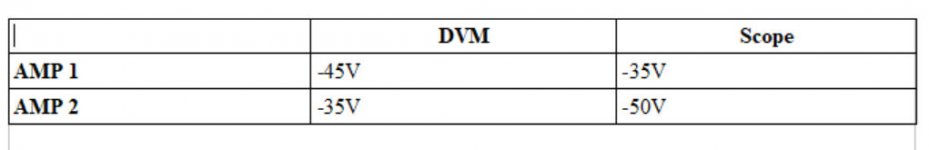
Ok, following up. When I used my scope to check the peak DC voltage at C410 in Amp 2 (Good amp), I see approximately -50V.
So these are the measurements at C410 in both amps. It's almost as if NAD measured the -35V figure on the two versions of the schematic in two different ways, with a DVM for the earlier iteration of the amp (Amp 2), and with a scope for the later (Amp 1).
So these are the measurements at C410 in both amps. It's almost as if NAD measured the -35V figure on the two versions of the schematic in two different ways, with a DVM for the earlier iteration of the amp (Amp 2), and with a scope for the later (Amp 1).
Attachments
I don't know what to say to those readings. I would need to go through it one step at a time and see where the difference occurred, if necessary adding part by part onto that cap.
Same AC voltage, same diode, same cap... that has to give the same starting point. Load each with a test resistor and confirm the results are identical. The remove the test resistor and build the circuit up.
Same AC voltage, same diode, same cap... that has to give the same starting point. Load each with a test resistor and confirm the results are identical. The remove the test resistor and build the circuit up.
I don't know what to say to those readings. I would need to go through it one step at a time and see where the difference occurred, if necessary adding part by part onto that cap.
Same AC voltage, same diode, same cap... that has to give the same starting point. Load each with a test resistor and confirm the results are identical. The remove the test resistor and build the circuit up.
But not the same cap.
Amp 2 originally came with a 0.47uF at C410, and Amp 1 came with a 1uF. I just replaced the 0.47uF in Amp 2 with a 1uF (both now the same) and rechecked the voltages. Now both amps measure approx. -45V with a DVM and -35V with the scope.
OK, so it is just the cap value causing the different results.
(It's hard following all the twists and turns from lots of posts sometimes as I thought the cap value difference had been eliminated from our enquiries a little while ago 😀)
So all good now in that area.
(It's hard following all the twists and turns from lots of posts sometimes as I thought the cap value difference had been eliminated from our enquiries a little while ago 😀)
So all good now in that area.
Thanks for the response and analysis!
Regarding whether my DVM will show the correct/real voltage at C410, I have another NAD 2200 here that I decided to check in the same spot. (This, too, has a single bad relay.) With this amp, I do actually read -35V at the cap.
So that got me wondering what, if any, differences there are component-wise between the two, at least in that part of the circuit.
Amp 1 (the one showing -45V):
C410: 1uF 100V (original)
Q403: RCA SK3245 (appears to be non-original)
Amp 2 (the one showing -35V):
C410: 0.47uF 100V (original)
Q403: 2SC2240 (original)
Otherwise the resistor values are the same. So not sure that anything there would really explain the -35V vs -45V discrepancy.
Fwiw, I also checked the voltages for Q402 and Q403 in Amp 2.
Q402
E +1.07
B +1.2
C +62.5
Q403
E 0
B -7.3 This voltage level are too close to the damaging level of the transistor parameters.
C +1.1
But not the same cap.
Amp 2 originally came with a 0.47uF at C410, and Amp 1 came with a 1uF. I just replaced the 0.47uF in Amp 2 with a 1uF (both now the same) and rechecked the voltages. Now both amps measure approx. -45V with a DVM and -35V with the scope.
Parity at last 😉
OK, so it is just the cap value causing the different results.
(It's hard following all the twists and turns from lots of posts sometimes as I thought the cap value difference had been eliminated from our enquiries a little while ago 😀)
So all good now in that area.
Yes, I made things a bit convoluted, didn't I? 🙂
Thanks for your help. Now I know how I should (and shouldn't) try to measure a half-wave rectified pulse, among other lessons.
Parity at last 😉
And thanks to you, too. Your suggestion to swap in that 1uF cap was on the mark, even if I didn't act on it at first.
- Home
- Amplifiers
- Solid State
- NAD Protection Circuit