Actually, that description of what the relays are doing wasn't as clear as it could have been.
One relay is operating normally. It clicks in a few seconds after power on and immediately at power down.
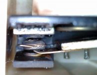
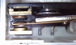
The other relay was not clicking in after power on or at power off. As a result, I was seeing significant DC voltage at the speaker terminals, e.g. up to -95V at power down, before the caps drained. After tapping the relay case, I got it to click in, but not consistently. So I opened it up for inspection. The bad one is on the left (obviously). Needless to say, new relays are en route.
One relay is operating normally. It clicks in a few seconds after power on and immediately at power down.
The other relay was not clicking in after power on or at power off. As a result, I was seeing significant DC voltage at the speaker terminals, e.g. up to -95V at power down, before the caps drained. After tapping the relay case, I got it to click in, but not consistently. So I opened it up for inspection. The bad one is on the left (obviously). Needless to say, new relays are en route.
Attachments
Are you sure you haven't a real DC offset fault here?
The relays can not operate separately, if one is energised then so is the other.
Not clicking audibly could be because the contacts are frazzled but electrically it is wanting to close. Actually even the lower part of that relay looks in bad shape, the arm holding the contact.
The relays can not operate separately, if one is energised then so is the other.
Not clicking audibly could be because the contacts are frazzled but electrically it is wanting to close. Actually even the lower part of that relay looks in bad shape, the arm holding the contact.
Ok, I visually observed the relay contacts, while monitoring the DC at the speaker terminals.
A few seconds after power on, both energize. At power off, both de-energize. I think you're right that I wasn't hearing the click because of how deformed the bad one is. In addition to what's shown in the photo, the plastic area above the contact is blackened from the arcing.
Anyway, back to -45V. . . .
So apart from the worn out relay they are clicking in a few seconds after power on and immediately clicking off when power is removed. It's working as intended.
If the amplifier works without DC offset when they are turned on, and everything has stabilised, what's the problem?
I know the -45V is odd but that specific node is going to be very prone to voltage shifts with very small changes in the current going through any of the surrounding parts, or the voltages supplying them.
Wait a second do we actually have a problem?
The diode is being fed 46VAC so rectified would be giving about -63V with no load connected. The greater the load the less negative the voltage will appear. The same is true for the smoothing cap. If the load remains the same but the smoothing goes down the average voltage will go less negative.
This is exactly what we're seeing.
The 'faulty' amp has a 1uF cap with a voltage of -45V.
The other amp has a 0.47uF cap with a voltage of -35V.
Smaller cap/less smoothing will give a voltage with less negative potential.
Take that 1uF Nichicon KL and put it in the other amp and see if the voltage drops down to ~45V.
If the voltages on the NAD schematic were characterised with the component values it also shows then that could be your answer.
Did you check what I suggested earlier for the -45V
Yes, posted on the previous page.
The secondary winding voltage going to D402 is 46VAC in both amps.
The collectors of Q337 and Q338 are showing -0.7V, both amps.
So apart from the worn out relay they are clicking in a few seconds after power on and immediately clicking off when power is removed. It's working as intended.
If the amplifier works without DC offset when they are turned on, and everything has stabilised, what's the problem?
I know the -45V is odd but that specific node is going to be very prone to voltage shifts with very small changes in the current going through any of the surrounding parts, or the voltages supplying them.
I can accept that the -45V is nothing to worry about, if that's the conclusion we're arriving at. Normally when I see a voltage spec'd for a particular measuring point in a schematic I accept a variation of +/- a volt or three. But in this case, 10V raised an eyebrow and seemed worthy of investigation.
Well lets try the thing with the cap I mentioned above and see what happens. Put the 1uF into the amp with the -35V and see if it goes down to around -45V. The -35V is the one with the 0.47uF cap currently right?
Well lets try the thing with the cap I mentioned above and see what happens. Put the 1uF into the amp with the -35V and see if it goes down to around -45V. The -35V is the one with the 0.47uF cap currently right?
Correct. I'll give that it a try.
Yes, posted on the previous page.
Thanks, I missed that.
The theory is sound as to what the this -45/35 volts 'should' be. It will be a voltage equal to the peak of the applied AC.
Is it possible there have been production changes and the values of the resistors loading that point are different between the two amps?
Thanks, I missed that.
The theory is sound as to what the this -45/35 volts 'should' be. It will be a voltage equal to the peak of the applied AC.
Is it possible there have been production changes and the values of the resistors loading that point are different between the two amps?
I compared all of the resistors in the protection circuit between the two amps and then checked them against the schematic. The only discrepancy is R412, though it doesn't seem like that would make a difference.
"Bad" amp (-45V): 18k
"Good" amp (-35V): 22k
Schematic: 22k
You have to check them out of circuit but I can't see that one doing anything...
Lets look at it like this.
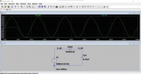
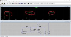
1/ You have 46 volts AC from the transformer. That means a sine wave of 46 volts RMS or alternatively a 65 volt peak (130 volt peak to peak) voltage. Image 1 shows this voltage. The diode conducts on the first negative half cycle and charges the cap to the peak (negative) voltage.
2/ The cap is loaded down by various resistors. Image 2. Q403 is a bit of a balancing act with R414 feeding in +62 volts from the main rail.
So this shows how the voltage would be on a scope.
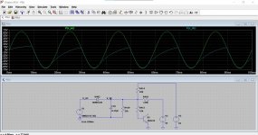
3/ R418 and pin 1 of the chip. Those overcurrent transistors in the power amps can only apply 95 volts via the 180k's into pin 1. The chip would clamp that but lets be silly and apply 95 volts. Image 3
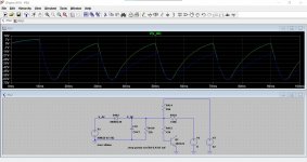
The effect of this is subtle. The transistor Q403 is now brought into conduction. Image 4 and 5.
The base /emitter volts is now pushed into conduction clamping at around 650 millivolts. That would light the LED it drives.
None of which explains the difference you are seeing between the two amps 🙂 You would have to use the scope to look at the waveforms and compare and see why it is as it is.
Lets look at it like this.
1/ You have 46 volts AC from the transformer. That means a sine wave of 46 volts RMS or alternatively a 65 volt peak (130 volt peak to peak) voltage. Image 1 shows this voltage. The diode conducts on the first negative half cycle and charges the cap to the peak (negative) voltage.
2/ The cap is loaded down by various resistors. Image 2. Q403 is a bit of a balancing act with R414 feeding in +62 volts from the main rail.
So this shows how the voltage would be on a scope.
3/ R418 and pin 1 of the chip. Those overcurrent transistors in the power amps can only apply 95 volts via the 180k's into pin 1. The chip would clamp that but lets be silly and apply 95 volts. Image 3
The effect of this is subtle. The transistor Q403 is now brought into conduction. Image 4 and 5.
The base /emitter volts is now pushed into conduction clamping at around 650 millivolts. That would light the LED it drives.
None of which explains the difference you are seeing between the two amps 🙂 You would have to use the scope to look at the waveforms and compare and see why it is as it is.
Attachments


Thanks for taking the time to put together that Spice model.
Re the resistors, I eyeballed their bands, so R412 is theoretically an 18k. Fwiw.
I'll check the waveforms with my scope, though it doesn't bode well that we've all run out of theories as to what might be causing the voltage difference. To recap, I've replaced D402, C410, and Q403, and checked R414, R415, R418, and R419 out of circuit.
I do still need to try the suggestion of 5th Element and move the 1uF cap to the good amp. Speaking of which, I did just find a different schematic for later serial number versions of the 2200, which is what the Bad amp is. Apparently, C410 was "officially" changed from 0.47uF to 1uF during the production run. This schematic does, however, still specify -35V.
🙂 all good fun.
The scope should definitely show what is happening. The diode has to produce a half wave pulse equal to the peak of the incoming AC. The cap has to smooth it to pure DC, which would be -65 volts. The we add the loading... and see where it all falls apart.
Let me run a 0.47uF vs 1uF for interest.
The scope should definitely show what is happening. The diode has to produce a half wave pulse equal to the peak of the incoming AC. The cap has to smooth it to pure DC, which would be -65 volts. The we add the loading... and see where it all falls apart.
Let me run a 0.47uF vs 1uF for interest.
thanks to @mooly and @5th element for such a great analysis of the protection circuit and relay drive.
Both the 2660 and 2700 specify and use the 1uf value, which if I have understood determines timing - that said I an with @dbxdx5 in not undertanding why there is a 10v difference.
I have a problem child 2200 (NAD 2200 wrong rail voltages) and a 2700 that I am working on and will report back on voltages.
As to versions, there are 4 versions of the 593 main boards, 593 and then 593A,B and C- which versions are in amps 1 and 2?
so the problem child NAD 2200 also has -45v as described by @dbxdx5- the circuit board is a 594A and the main boards are 593A. The protection works fine, although there is the rail problem in the right channel. It has new relays, and caps.
the 2700 has -33.5v- which implies that -35v is the correct voltage, and thus the -45 could be indicative of another fault as @dbxbx5 suspected.
Here we go. Blue is the 1uF
Ok, thanks for modeling this.
One other difference between the protection circuits in the two amps that I just noticed. In the Good amp, the 0.1uF 100V film caps C415 and C416 shown across the relay outputs are present, but they've been deleted in the later version Bad amp. Again, it doesn't seem like this would play any role in the voltage issue, but I do wonder why they were eliminated.
thanks to @mooly and @5th element for such a great analysis of the protection circuit and relay drive.
Both the 2660 and 2700 specify and use the 1uf value, which if I have understood determines timing - that said I an with @dbxdx5 in not undertanding why there is a 10v difference.
I have a problem child 2200 (NAD 2200 wrong rail voltages) and a 2700 that I am working on and will report back on voltages.
As to versions, there are 4 versions of the 593 main boards, 593 and then 593A,B and C- which versions are in amps 1 and 2?
Thanks Peter.
Amp 1 (the "Bad" -45V one) has the 593B boards.
Amp 2 (the "Good" -35V one) has the 593 boards.
so the problem child NAD 2200 also has -45v as described by @dbxdx5- the circuit board is a 594A and the main boards are 593A. The protection works fine, although there is the rail problem in the right channel. It has new relays, and caps.
Interesting. Thanks for checking this. Is the serial number for this amp higher than 6010010? As you probably know, this is the threshold for which amps should use the other 2200 service manual.
It could be that this amp and my "bad" one both have the same underlying fault. Or it's possible that there was a change to the circuits of the later version 2200s that resulted in -45V at that measuring point, and the figure was never updated from -35V on the revised schematic.
- Home
- Amplifiers
- Solid State
- NAD Protection Circuit