Idle means no signal, no speakers connected usually.What does 'at idle' mean? I wonder if I was checking it properly.
If you're a bit stuck perhaps try removing one electrolytic at a time off that -26v rail and see what happens to the voltage drop across that resistor (perhaps jot it down). I would probably look to replace them all anyway, but if you don't have replacements to hand this might give you a clue as to whether one or several are contributing to the problem. If none make a difference then they are not the issue.
Someone rightly pointed out the components driving the +26v rail are also looking heated so you might have something similar going on there. But start with the most obvious issue and see where it leads you.
Idle means no signal, no speakers connected usually.
If you're a bit stuck perhaps try removing one electrolytic at a time off that -26v rail and see what happens to the voltage drop across that resistor (perhaps jot it down). I would probably look to replace them all anyway, but if you don't have replacements to hand this might give you a clue as to whether one or several are contributing to the problem. If none make a difference then they are not the issue.
Someone rightly pointed out the components driving the +26v rail are also looking heated so you might have something similar going on there. But start with the most obvious issue and see where it leads you.
thanks, I'll double check it as I did have speakers connected. Should the volume be all the way done and nothing on the audio input at the time of the test?
Just so I'm clear, you are saying to disconnect capacitors connecting to that -26V line one by one and see if it changes the non -55V side of the resistor that is getting hot? I'd want to see the voltage on that 'low side' go up right? That would make the drop across the resistor less?
I did test the leg of Q42 (next to hot resistor) and it is reading -26V, which I think is good?
thanks, I'll double check it as I did have speakers connected. Should the volume be all the way done and nothing on the audio input at the time of the test?
Yes. It's unlikely speakers connected or not will matter to these measurements but they will matter when you come to perform the alignment (once you're done repairing)
Just so I'm clear, you are saying to disconnect capacitors connecting to that -26V line one by one and see if it changes the non -55V side of the resistor that is getting hot? I'd want to see the voltage on that 'low side' go up right? That would make the drop across the resistor less?
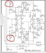
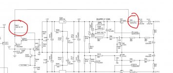
Measure from one leg of the resistor to the other (green arrows). The difference will tell you how much current is passing through it.
Most of the difference between the -55v to -26v should be happening in the transistor, but it will vary its effective resistance depending on load automatically, in order to keep the emitter (orange) at -26v.
I did test the leg of Q42 (next to hot resistor) and it is reading -26V, which I think is good?
Depends which leg you measured, but assuming the one you got is the emitter (marked orange) then that is expected as explained above.

Thanks Mooly, if that is the case should I order a 2 watt resistor ( or 50! Lol) to replace it with? Or leave the one in it?
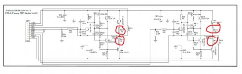
I've had a good look at the full circuit and it seems the -/+18 volt rails supply the analogue audio stages which also includes discrete circuitry.
The big question is whether something is drawing to much current and that tbh is not easy to check. If you had just 7 volts across the resistor then it would be within its rating... so we are talking only small variations here.
And it may well still be normal...
The only tests I could suggest would be comparing left and right channel currents by measuring volt drops across key resistors in the analogue stages and seeing if one channel was drawing more than the other.
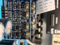
For example (first image is of one channel only), second image has both on the one board. So eight measurements here in total.
You could replace the resistor with a series/parallel arrangement of your 51 ohms quite neatly by mounting them vertically, at least for testing. Two 51 ohms in series is 102 ohm. You then parallel that by another series pair bringing the overall value back to 51 ohm. The power in each resistor is then just 0.3 watt.
Usual disclaimer on that... the fusible is a safety rated part and has characteristics that make it fail cleanly and with no signs of smoke or burning smell. Ordinary resistors burn and smoke when overloaded... which scares customers and is one reason for the use of fusibles.
Attachments
Im late to this party but.. dropping 55v down to 26v... yeah, somethings going to get hot. I would fit a 3W cement resistor and forget about it 🙂
Thanks everyone for the suggestions, and dialog. You've all been very helpful. I'll be back home tonight and will do these tests and post back my results!
As Mooly pointed out, the voltage is actually pretty close to being in spec. I'll also have access to my better quality meter tonight and will do the test with a bit more precision.
Thanks again for the help and support!
- Craig
As Mooly pointed out, the voltage is actually pretty close to being in spec. I'll also have access to my better quality meter tonight and will do the test with a bit more precision.
Thanks again for the help and support!
- Craig
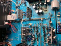
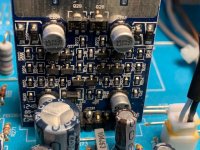
Okay folks, I'm back. I ran the test Mooly mentioned. There were two of both boards you pointed out. And the components are tiny. LOL.
I've attached a photo that shows all four, and close ups of the two styles of board.
I tested the voltages on either side of the resistors with teh volume down and no speakers attached. I got the below readings:
Board 1:
R255: 18.09, 18.09
R254: 17.78, 17.78
Board 2:
R155: 18.14, 18.14
R154: 17.79, 17.79
Board 3:
R615: 325.8mv, .468v
R616: .444v, 298.5mv
R617: 154.5mv, 254mv
R618: 177.5mv, 320mv
Board 4:
R615: 269.7mv, .417v
R616: 387.5mv, 248.8mv
R617: 109.7mv, 248.4mv
R618: 126mv, 269.2mv
I retested R46 with my better meter here are the readings:
R46: -54.4, -47.3
Again, this is with no speakers connected, no source coming in, and the volume down. This is also still with the resistor that I put in (the replacement) that has discolored... So 7.1 volts of drop.
Thanks for the continued help all. What do you think? Were you guys serious about the 3watt resistor? Does the measurements here look like they just were a bit off on the spec of a 1 watt resistor, or does it look like downstream issues? If it looks like we may want to just go with a larger resistor I'd rather a 2 watt if I can get away with it as they are way cheaper than 3 watt... I'm also okay with using 4 of the 51ohm units I have on hand. I had actually had that same idea when I was thinking of a way to cool this thing down. Not sure how I'd get 4 resistors jammed in there though! 🙂
I haven't done the capacitor tests yet that someone mentioned, but will if we think it makes sense at this point. Measuring these resistors is easier than pulling a bunch of caps.
Attachments
Nothing looks wrong there.
Need to have another look at the circuit diagram but do try and eliminate those electrolytics, they do tend to start leaking current with age.
Need to have another look at the circuit diagram but do try and eliminate those electrolytics, they do tend to start leaking current with age.
Very unlikely and a bad idea with metal film resistors. That may be the old way from the days of carbon resistors but it doesn't make sense here, since the manufacturer is already fitting fusible resistors elsewhere - that's what they're for.This resistor may be underrated so that it will blow and protect other things under a fault condition.....
Per my later comment, in the circuit diagram the resistor in question is marked fusible .. so it did likely blow in response to a fault condition
I agree that all those volt drops are looking OK.
The resistor you've fitted looks like a metal oxide type and its normal for these to discolour quite badly when run hot and up to their limits. I've seen that countless times on older TV's and the like.
The big question is whether we are chasing a subtle problem here, or whether its just 'normal'. 7.1 volts drop is pretty much dead on 1 watt dissipation.
I suspect looking to locate and add up all the currents from that supply to see what is going where isn't something you are keen on doing.
You could try heating those boards with the little electrolytic cans on them using a hairdryer and seeing if the volt drop across the 51 ohm altered... I still think this is all bordering on 'normal' though.
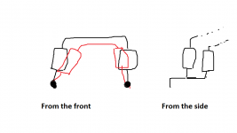
Four resistors... bend the leads neatly for one pair and mount them vertically. Add a bend so it moves them forward into that empty space. Then add a second parallel pair by wrapping and soldering to the first pair.
Like this, rubbish drawing 😀
The resistor you've fitted looks like a metal oxide type and its normal for these to discolour quite badly when run hot and up to their limits. I've seen that countless times on older TV's and the like.
The big question is whether we are chasing a subtle problem here, or whether its just 'normal'. 7.1 volts drop is pretty much dead on 1 watt dissipation.
I suspect looking to locate and add up all the currents from that supply to see what is going where isn't something you are keen on doing.
You could try heating those boards with the little electrolytic cans on them using a hairdryer and seeing if the volt drop across the 51 ohm altered... I still think this is all bordering on 'normal' though.
Four resistors... bend the leads neatly for one pair and mount them vertically. Add a bend so it moves them forward into that empty space. Then add a second parallel pair by wrapping and soldering to the first pair.
Like this, rubbish drawing 😀
Attachments
Nothing looks wrong there.
Need to have another look at the circuit diagram but do try and eliminate those electrolytics, they do tend to start leaking current with age.
I've just been rereading your posts around the caps. So, do I have this right: since this is all DC there really shouldn't be any current flowing through the caps (you have circled), or at least once they charge up there shouldn't be. But if one is old and 'leaking' then DC is passing. That passing, or leaking, current then causes a drop on the -26v line, which Q42 then works to replace. In the end all of this has the net effect of causing more current to pass through R46 then we want, and it was designed for, causing it to go over 1watt. Do I have the thinking basically right here? I could be way wrong here though! 🙂
Interesting that you and Mooly are attacking, what to a novice, looks like dramatically different 'areas'. Can Mooly, or anyone, help me understand how the 4 daughter boards he has me checking relate to this part of the circuit?
Thanks for the continued help. And please no one take any offense from my questions... I'm just trying to learn a bit!
- Craig
Those boards run on -/+ 18 volt which is derived from the -/+ 26 volt rails. Any increase in current drawn by the rails would automatically increase the current in the 51 ohm by the same amount.
An idea! if you want to try it, but it would need care in implementation. If a meter on its current range were inserted in series with the emitter of Q41 then we could compare the current draw of the pos and neg rails which normally are pretty equal in most designs. It would have to be done with soldered leads from the board and transistor leg to the meter to ensure 100% connectivity at all times. It would be a fairly definitive test as to whether a rail cap was at fault.
All those caps connected across the rails pass no DC current and so should add nothing to the overall current consumption.
Lets just throw some numbers and ideas into that. Lets say that a cap was leaky.
A thought experiment as to the real and normal current in the 51 ohm. Suppose NAD set the normal resistor dissipation at 0.8 watts. That would suggest a normal current of 0.125A as against a current of 0.14A required to achieve the 1 watt max dissipation. That difference is little more than a standard LED would draw.
You measured 7.1 volts which is in fact a current of 0.140A
So 0.140-0.125 is only 15 milliamps difference between a comfortable 0.8W vs 1W maximum. At 18 volts that 15 milliamps would generate 0.27 watt of heat which might well be discernible with a finger on a cap. Also bear in mind that for the fusible to fail it would need over 1W for a certain time period... how long depends on the overload but I would imagine it would run for a long time at say 1.1 watt which would be a current of 0.147A. That difference would generate 0.4W in the leaky cap.
And remember, you know what 1W feels like because of the 51 ohm. In a small component its hot!
(bit of a waffly post 😀 but it might help with some perspective.. I'm inclined to say do the resistor mod and use the amp and then at some future date see if the volt drop across the 51 ohm has changed)
Q41? Or Q42?An idea! if you want to try it, but it would need care in implementation. If a meter on its current range were inserted in series with the emitter of Q41 then we could compare the current draw of the pos and neg rails which normally are pretty equal in most designs. It would have to be done with soldered leads from the board and transistor leg to the meter to ensure 100% connectivity at all times. It would be a fairly definitive test as to whether a rail cap was at fault.
This is very helpful! Thanks for the help!A thought experiment as to the real and normal current in the 51 ohm. Suppose NAD set the normal resistor dissipation at 0.8 watts. That would suggest a normal current of 0.125A as against a current of 0.14A required to achieve the 1 watt max dissipation. That difference is little more than a standard LED would draw.
You measured 7.1 volts which is in fact a current of 0.140A
So 0.140-0.125 is only 15 milliamps difference between a comfortable 0.8W vs 1W maximum. At 18 volts that 15 milliamps would generate 0.27 watt of heat which might well be discernible with a finger on a cap. Also bear in mind that for the fusible to fail it would need over 1W for a certain time period... how long depends on the overload but I would imagine it would run for a long time at say 1.1 watt which would be a current of 0.147A. That difference would generate 0.4W in the leaky cap.
And remember, you know what 1W feels like because of the 51 ohm. In a small component its hot!
I did a temp check on the caps in the area. C410 felt the warmest other than C43 and C44 which are both pretty hot. I took C410 out and still have 7.1 Volt drop on R46.
I also put a bright light under the board and noticed the trace from the Q42 to R46 is turning dark in color, so we are certainly running some juice across that one.
Looking at the board I was again reminded that R45 and D110 are also very hot, to the point they are also turning my circuit board weird colors as I do these tests! 🙂
Would there be anything that is common between the +55VA and -55VA sides in this area that could be impacting both? Seems like they are both having issues. The thing still smells hot within second of me turning it on.
I'm willing to take a stab at pulling Q41 out if I can figure out a way to get my meter in there. Please just confirm for me that you want me to test Q41 and not Q42.
I was all ready to just rig this up with 4 of these 51 ohm resistors but I just a touch hesitant. Though the longer I sit here tonight I may end up just doing it and seeing if the smell goes away. maybe I just smell that R46 resistor.
Q42 we already know the current in, its the same as the 51 ohm.
Q41 is different because although there is a resistor present (R45, 3.3 ohm) there appeared to be a another take off point after that resistor that would add to the total current in that resistor...... and I was just looking at the snip of the power supply you posted at the beginning.
An easier way looking at the full diagram. The 3.3 ohm also feeds the 12 volt regulator via R427.
1/ Measure the volt drop across R427 and calculate the current.
2/ Do the same for R45.
3/ Subtract the first value (R427 current) from the current in R45 and that will leave the current flowing in Q41.
I would expect that calculated current to be similar to the value you see in the 51 ohm.
Caps themselves should run cold but obviously they can get heated via other parts close by. PCB discolouration is normal as well and is a chemical response in the board material to the heat.
Lets see what you come up with first but I'm still erring to view that this is normal.
(I've seen parts run that hot (by the circuit design) that the manufacturers have had to issue bulletins to resolder parts using high temperature solder because they were literally desoldering themselves. You wouldn't believe how hot some stuff actually runs, and that is normal if poor design)
Attachments
Thanks all for the help. I've rigged up the 4 51Ohm resistors for now. System is up and running I'm in the process of letting it do a burn in to see if anything else blows up. Here's hoping for the best!
I'll try to make sure to post back in a week or so and let you know if it worked!
Thanks so much for the help everyone, I learned a lot and am hopeful that this has resolved my issues!
I'll try to make sure to post back in a week or so and let you know if it worked!
Thanks so much for the help everyone, I learned a lot and am hopeful that this has resolved my issues!
Well  I think this will probably be fine (really) but for interest and when faced with difficult faults... blowing them up or leaving to see 'what burns' is a valid method that can save hours of troubleshooting something that isn't always apparent or on something very intermittent.
🙂 you'll be fine.
I think this will probably be fine (really) but for interest and when faced with difficult faults... blowing them up or leaving to see 'what burns' is a valid method that can save hours of troubleshooting something that isn't always apparent or on something very intermittent.🙂 you'll be fine.
- Home
- Amplifiers
- Solid State
- NAD Amp Repair (Newbie)