By adjusting the output of the signal, I redid the test so that the amp would be set to approx 50% volume, and then again so that the amp would be set to about 95% volume. Here's the results... (low gain/mid gain/high gain)
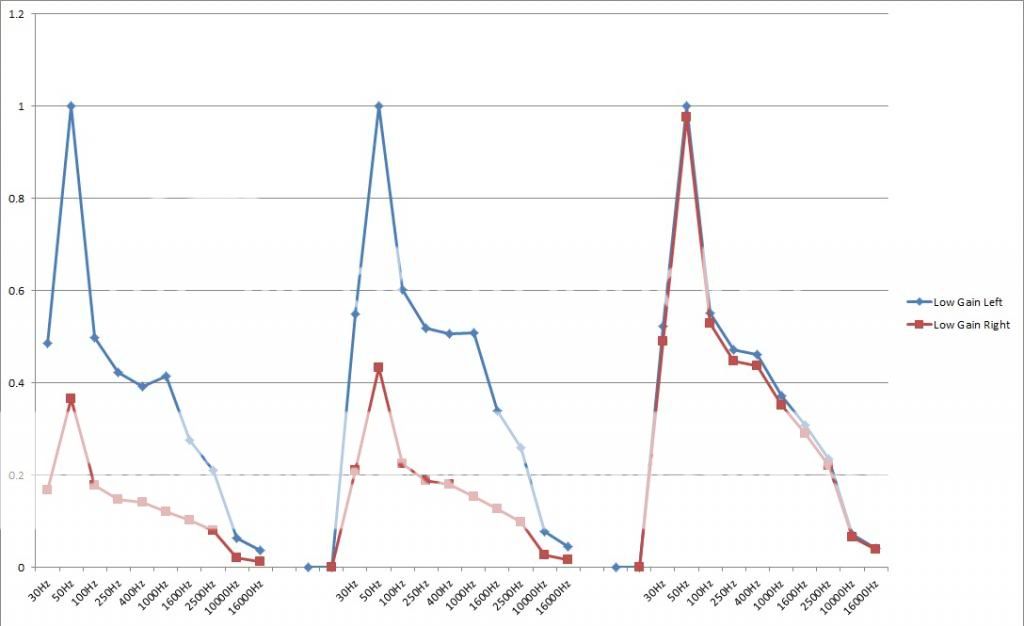
Very strange result but it does seem to show a problem around the input of the amp. Did you try it with those two diodes isolated ?
It looks like the input impedance of the two channels is different and as the volume control is rotated further and further then the difference becaomes less.
It looks like the input impedance of the two channels is different and as the volume control is rotated further and further then the difference becaomes less.
Only two components set the "gain" of the whole amp, the ratio of the two resistors circled. The two diodes look to be some form of switch on (or off) noise suppression. Might be worth lifting those two diodes and retesting. I can't see it would cause any issues. The other two diodes go to the other channel. If one were leaky it would form a divider and reduce the input level so worth looking at.
I went ahead and pulled up diodes D701, 702, 703, and 704. all test good. I pulled Q701, it checked good.
You mentioned that the ratio between the resistors R616 and R617 set the gain for the whole amp. I pulled R616/617(left channel) and R666/667 (right channel) While I was at it, I checked C657(right) to compare its value to C607(left)
What I got was this:
R616: 670-------R666: 670---------Should be 680
R617: 15.2K-----R667: 15.05K-----Should be 15K
C607: 232uF-----C657: 136.3uF----Should be 220uF
Prior to me lifting diodes and applying power. What you described is that D701, 702, 703, and 704 all can be removed from the circuit with no ill effect? If so, I'll lift one leg of each diode and retest. I just want to confirm before I try that...
One step at a time 🙂
The fact the levels are the same at high volume means the basic gain of the amp is fine.
The effect you are seeing is what would happen if (say) R601 or R604 were low in value. (They are just examples).
Its a very unusual issue. I think you have to try either with those diodes removed or replaced as a first step. Everything around those transistors has to be OK because they are common to both channels.
A leaky cap could cause it. There are a couple that go to ground on the input.
Try and imagine a dual 10K pot (the volume control) and the wiper of one channel feeds into a 100K resistor to ground. The wiper of the other channel feeds say 20K to ground.
As the pot is turned the wiper of each will have a different voltage due to the different resistances (just ohms law) but as the pot is turned up to full, the effect diminishes and at full volume the full input voltage is delivered to each.
That is what seems to be happening here.
As the pot is turned the wiper of each will have a different voltage due to the different resistances (just ohms law) but as the pot is turned up to full, the effect diminishes and at full volume the full input voltage is delivered to each.
That is what seems to be happening here.
Just an example I know... But if I didn't test them I'd wonder...
R601: 219.5K (220K)
R604: 38.6K. (39K)
R601: 219.5K (220K)
R604: 38.6K. (39K)
Nah 🙂
We are talking a big discrepancy somewhere. R604 would have to be (guessing) say 10K to give an effect like you have.
Try it with those diodes pulled out on that channel.
We are talking a big discrepancy somewhere. R604 would have to be (guessing) say 10K to give an effect like you have.
Try it with those diodes pulled out on that channel.
Not the best way but with everything back in place and keeping the meter leads the same between both channels just try some resistive checks in circuit around the input stage.
Whoop... Pulling those diodes = baaaaad idea.
Even at lowest volume, as soon as the relay clicks, there's a very loud ~80hz buzz
Even at lowest volume, as soon as the relay clicks, there's a very loud ~80hz buzz
Baaah, disregard that last post... R601 and R604 were still lifted. They're back down and it's quiet with the diodes lifted
Alright, I went ahead and did the check. The results were quite different with those diodes out of the circuit. The response at 50Hz was pretty bizarre...
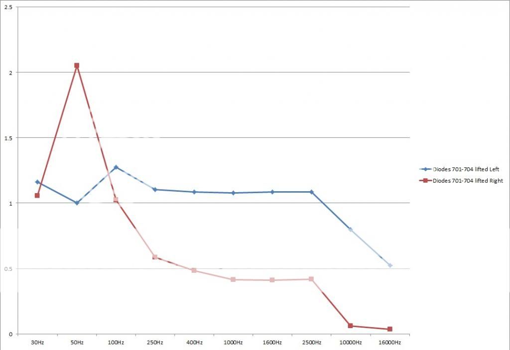
The right channel seems to have come up in amplitude compared to the graphs in the earlier post where it was the lowest.
I would check you haven't missed anything on the left channel as something seems to have gone amiss there since last time. Those diodes should have no effect on a correctly working amp whether fitted or not.
I would check you haven't missed anything on the left channel as something seems to have gone amiss there since last time. Those diodes should have no effect on a correctly working amp whether fitted or not.
Yeah, looking at the chart, it seems like the left channel has been dampened. I imagine if I had set it up with the Right channel, 1v @50hz, it would have looked the same as it did in the test prior to lifting the diodes. The Left channel changed its whole curve.
I will reconnect the diodes to make sure it goes back to how it was, then perhaps work from there.
So, the question is... By lifting the diodes and removing that suppression circuit from the amp, did it exacerbate the underlying discrepancy? That perhaps the suppression circuit was making up for the defects caused someplace else in the left channel's circuit?
You have to back track a bit and get it as it was before.
It looks from the last graph that the faulty right channel has come up with the diodes lifted. You need to repeat exactly what you did in post #41 to confirm and then see if you can find out was has happened since.
Just lift all four diodes and try it the amp out.
It looks from the last graph that the faulty right channel has come up with the diodes lifted. You need to repeat exactly what you did in post #41 to confirm and then see if you can find out was has happened since.
Just lift all four diodes and try it the amp out.
You have to back track a bit and get it as it was before.
It looks from the last graph that the faulty right channel has come up with the diodes lifted. You need to repeat exactly what you did in post #41 to confirm and then see if you can find out was has happened since.
Just lift all four diodes and try it the amp out.
That test that I did was with all four diodes lifted so that the effect could be matched between the two channels
It seems with all four diodes lifted, the right channel has the same curve as it did in previous tests, the left channel changed its curve along the whole spectrum
You need a scope 🙂
Its a case of measuring the signal applied to both the power amps before and after the input filter... see whats going on, see where things are changing.
I'm still not convinced about whats going on around those diodes.
Its a case of measuring the signal applied to both the power amps before and after the input filter... see whats going on, see where things are changing.
I'm still not convinced about whats going on around those diodes.
I just finished repairing a sub for a friend and deposited that money into my scope fund 🙂
I did like your simplified description of th action of the resistors and caps to ground... I think, unless I find a failed resistor that I haven't yet checked, I'm going to replace all those caps.
I did like your simplified description of th action of the resistors and caps to ground... I think, unless I find a failed resistor that I haven't yet checked, I'm going to replace all those caps.
- Status
- Not open for further replies.
- Home
- Amplifiers
- Solid State
- NAD 7250PE no service manual