What's odd is that the RH channel with the new power transistors sounds much cleaner and more well-rounded. The LH channel has way too much treble, and virtually no bass at all. One thing that I did on the LH channel that I didn't do on the right was install a new potentiometer in place of the failed distortion potentiometer. I made sure it was set to 100ohms when I installed it, but when I found that same potentiometer failed on the RH channel, I got lazy, and tossed a 100ohm resistor in its space. It doesn't seem like this should do much, but I'm tempted to replace that pot on the LH channel with a 100ohm resistor...just for consistency's sake. Other than that, I'm tempted to replace the same power transistors on the Left channel, as I did on the Right channel.
It doesn't seem like it's one of the switches or potentiometers on the front panel, as actuating any of them doesn't cause a change for the better or worse on either channel, just an occasional crackle that comes from a switch that could use some cleaning.
It doesn't seem like it's one of the switches or potentiometers on the front panel, as actuating any of them doesn't cause a change for the better or worse on either channel, just an occasional crackle that comes from a switch that could use some cleaning.
This is where a scope is essential really. Without and you have to try and isolate the problem as far as possible. You could swap the left and right feeds to the power amps to try and see whether the problem is pre or power related. That has to be a first step I think, to isolate where the problem lies.
Oh, how often I think about how much benefit owning a scope would do me.... One day!! Too bad that's not today...
I digress. Great suggestion. I went ahead and removed the jumpers, and found that the problem exists in the main amp section. The music on the left channel is much more well rounded. I'm going to yank that distortion pot and put in a straight 100ohm resistor. If that doesn't fix it, I'll likely go after those power transistors.... Too bad I don't have a baseline to know if this was a discrepancy from before the failure that this stereo was given to me for!
I digress. Great suggestion. I went ahead and removed the jumpers, and found that the problem exists in the main amp section. The music on the left channel is much more well rounded. I'm going to yank that distortion pot and put in a straight 100ohm resistor. If that doesn't fix it, I'll likely go after those power transistors.... Too bad I don't have a baseline to know if this was a discrepancy from before the failure that this stereo was given to me for!
Have you tried swapping the speakers... have to ask 🙂
Transistors won't cause any alteration in tonal balance. If the bass is lacking then that points to a cap that is either low in value or that has been replaced withone of incorrect value. I haven't the circuit in front of me but look at the input coupling cap and any electrolytic cap in the feedback return.
Transistors won't cause any alteration in tonal balance. If the bass is lacking then that points to a cap that is either low in value or that has been replaced withone of incorrect value. I haven't the circuit in front of me but look at the input coupling cap and any electrolytic cap in the feedback return.
Not a silly question, I wondered about the speakers myself... I did swap them left and right, as well as A channel and B channel (just to rule that out) and the results were the same.
I have also been thinking about the caps. The only schematics I've had available, have been the ones I've posted in this thread.
I have also been thinking about the caps. The only schematics I've had available, have been the ones I've posted in this thread.
Yeah, for the number of broken electronics friends and family throw at me, I really should own a scope...I should start a fund... But until then, looks like I'm going to have a lot of soldering ahead of me! (None of the caps on the board were visually distorted)
This is where its all guesswork because literally two minutes with a scope would quantify what was happening. The basic amp has a response of DC to way over 20Khz and is "tailored" at both extremes by the value of coupling caps at LF and the time constant of any compensation caps and input filter networks at HF.
It could be unstable and oscillating giving a tinny sound, which although unlikely, we just don't know.
It could be unstable and oscillating giving a tinny sound, which although unlikely, we just don't know.
Well, I went ahead and pulled all the caps that you mentioned and this is the result:
Cap. Should be. Is.
C601. 100pF. 170pF
C602. 1uF. 1uF
C603. 1uF. .995uF
C604. 1.2nF. 1.34nF
C605. 820pF. 808pF
C606. 100pF. 160pF
C607. 220uF. 232uF
So, none are way off-spec. But some are more than they should be. Is it enough to cause an issue like this? (Goes back to the whole scope issue)
Cap. Should be. Is.
C601. 100pF. 170pF
C602. 1uF. 1uF
C603. 1uF. .995uF
C604. 1.2nF. 1.34nF
C605. 820pF. 808pF
C606. 100pF. 160pF
C607. 220uF. 232uF
So, none are way off-spec. But some are more than they should be. Is it enough to cause an issue like this? (Goes back to the whole scope issue)
They seem fine. From your description of the sound it would need for example the 220uf to be below 50 and the 100pf to be over 1000pf.
If you have a DVM that can measure AC voltages between say 30Hz and 10Khz (or you can calculate an error chart for its inaccuracies) then you could play test tones from CD and see if the amplitude differs at varying frequencies over that range. The output of the CD player is perfect over the whole audio range for a given level so the amp should follow and output the same.
Get a scope 😀
Oooooh, the scope. I still have my eyes on a Atten ADS1062CAL....
I wonder if I output from my iPhone, using a tone generation app various test tones, if it'll have the proper response...
I wonder if I output from my iPhone, using a tone generation app various test tones, if it'll have the proper response...
The app puts out 20hz to 20,000hz, sine, square, sawtooth(norm &rev), and triangle. I know sine is probably the way to go...but I figured I'd put it out there...
Yep, sine is the way to go.
If you want to test using your meter then here's what you have to do. The amp should have constant gain at all frequencies of course and so you could test by comparing the good channel to the bad. I would set the volume to give around 1 volt across 8 ohm on your meter at say 500 hz and then note the output at say 30hz, 100hz , 1Khz 10khz etc.
You could burn a test CDR using the free "Audacity" program with any frequencies you want or even a sweep. That would be far better I imagine than an phone app.
Audacity: Free Audio Editor and Recorder
You can burn a CDR using the free "Audacity" program
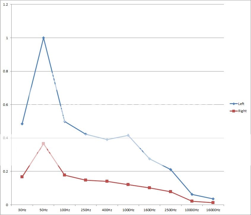
Alright, I went ahead and tested at a whole variety of tones, I setup @ 50hz since that's a frequency which the meter probably best responds at. I adjusted the volume to output 1v on the stronger channel. I also swapped L and R inputs to ensure that there wasn't a stronger output from the generator...the values remained the same regardless of which input I used.
L R
30hz 0.485v 167mV
50hz 1.000v 0.366v
100hz 0.499v 177.3mV
250hz 0.422v 147mV
400hz 391.4mV 140.3mV
1.6K 276.1mV 101.1mV
2.5K 211.0mV 78.7mV
16K 35.9mV 12.7mV
L R
30hz 0.485v 167mV
50hz 1.000v 0.366v
100hz 0.499v 177.3mV
250hz 0.422v 147mV
400hz 391.4mV 140.3mV
1.6K 276.1mV 101.1mV
2.5K 211.0mV 78.7mV
16K 35.9mV 12.7mV
That shows a lack of gain across the board.
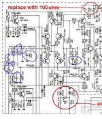
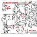
First thing to eliminate would be the possibility of poor tracking of the volume control if you did that test at a level that only needed the control turning a few degrees. Assuming that was all OK then its strange. Only two components set the "gain" of the whole amp, the ratio of the two resistors circled. The two diodes look to be some form of switch on (or off) noise suppression. Might be worth lifting those two diodes and retesting. I can't see it would cause any issues. The other two diodes go to the other channel. If one were leaky it would form a divider and reduce the input level so worth looking at.
First thing to eliminate would be the possibility of poor tracking of the volume control if you did that test at a level that only needed the control turning a few degrees. Assuming that was all OK then its strange. Only two components set the "gain" of the whole amp, the ratio of the two resistors circled. The two diodes look to be some form of switch on (or off) noise suppression. Might be worth lifting those two diodes and retesting. I can't see it would cause any issues. The other two diodes go to the other channel. If one were leaky it would form a divider and reduce the input level so worth looking at.
Attachments
One thing I wondered about but had no time to test is the impact of the speaker load. Tomorrow I'll swap the speakers and retest @1v.
To obtain 1v, it only required a couple of degrees of volume.
I'll also go ahead and check those components and see what their values are
To obtain 1v, it only required a couple of degrees of volume.
I'll also go ahead and check those components and see what their values are
- Status
- Not open for further replies.
- Home
- Amplifiers
- Solid State
- NAD 7250PE no service manual