Some wise guidance would be much appreciated.
I bought the 7240 new about twenty years ago and it has only had limited use with several periods of a few years inactivity.
Early on I remember it occasionally producing horrible distortion from the right speaker, normally after an hour or two's use. Turning the "soft clipping" switch on seemed to prevent the problem although it was never played very loud.
A few years ago it blew the four fuses (2 x 4A and 2 x 5A). It may or may not have been caused by a momentary short on the output. There were no obvious internal faults so rightly or wrongly I replaced the fuses (4 x 4 amp as that was all I had got). It was fine but after a few months it went back into storage.
It had been back in use for a few weeks playing low level classical music in my office. I thought I detected a slightly warm smell then it stopped working. Note this was only slightly warm, not hot or smoking!!
Again all four fuses had blown. A careful inspection found that one leg of the middle of the five heatsink mounted transistors (Q417) for the right channel was not soldered!! There was a slight groove in a blob of solder but it seemed to only make contact by pressure. To me this looks like a production fault, I don't think it has melted away in use. Some of the other soldering is pretty terrible!
I have soldered it in place and fitted 4 more 4 amp fuses. It seems to work fine again.
Have I found the symptom or the cause?
Anything else I should check?
I'm struggling to understand the first page of the service manual about setting the currents. Is this worth a check and if so, could some kind soul clarify the instructions for me please?
I see from Google I'm not the only person to struggle to understand that page of the manual!
Many thanks
Last edited:
Any thoughts on this one?
In particular regarding clarifying checking the current settings (manual reproduced below).
Centre voltage (A1) - Is that simply across the speaker terminals? Presumably with input shorted and min volume?
Idling Current (B1) - Would this be a short on the back of the board? I'm struggling to find any removable link.
Or, shall I just assume that all my problems were caused by the unsoldered lead on Q417 and leave well alone?
Thanks
Attachments

Q417 is the Vbe multiplier so poor soldering there would result in excessive quiescent current... so it looks like you've found the fault 🙂
The first part of the set up is just DC offset so adjust for 0.00 volts DC across the speaker terminals when the amp has been on for a while.
Second one is bias current. Removing the solder short puts a 1 ohm in series with the output transistors. So adjusting for 26 mv across the ohm gives a current of 26 milliamps. Leave the amp on (and no speakers) and keep tweaking until its around that figure at normal temperature. Leave the top on and then recheck after another 30 minutes or so. Then apply the short again of course.
Q417 is the Vbe multiplier so poor soldering there would result in excessive quiescent current... so it looks like you've found the fault 🙂
The first part of the set up is just DC offset so adjust for 0.00 volts DC across the speaker terminals when the amp has been on for a while.
Second one is bias current. Removing the solder short puts a 1 ohm in series with the output transistors. So adjusting for 26 mv across the ohm gives a current of 26 milliamps. Leave the amp on (and no speakers) and keep tweaking until its around that figure at normal temperature. Leave the top on and then recheck after another 30 minutes or so. Then apply the short again of course.
Thanks again for your advice Mooly, that is reassuring! It will probably be tomorrow before I get to this.
I don't know if I described the unsoldered lead correctly.
Each of the (5 per channel) heatsink mounted transistors has a slot in the PCB for the three leads rather than individual holes. They are then bent inelegantly at angles and soldered to the board. This lead looks as if it sprung just as the solder was setting. There was a clear groove in the blob of solder but the lead was simply touching the top of the groove and not attached at all!
The construction is all pretty horrible. Elsewhere a component has clearly been replaced and a bit of broken track bridged with 5mm of wire. Given that I bought this new and have never worked on it (apart from replacing fuses) it must have left the factory like that or been a dealer return.
Will my 4 amp fuses do or should I get two of the proper five amp jobs?
The fuses... hard to say. Haven't got the manual in front of me so can't see what they protect. They must be the correct type with regard to fast or anti-surge (time delay) specs. It should say on the PCB such as F5A or AS5A or T5A etc. Any fuses for the transformer primary should be the correct value although lower will just/or could cause random blowing at switch on. If the fuses feed into a large capacitor bank then they should be as recommended. Which they should be any way really 🙂
The fuses... hard to say. Haven't got the manual in front of me so can't see what they protect. They must be the correct type with regard to fast or anti-surge (time delay) specs. It should say on the PCB such as F5A or AS5A or T5A etc. Any fuses for the transformer primary should be the correct value although lower will just/or could cause random blowing at switch on. If the fuses feed into a large capacitor bank then they should be as recommended. Which they should be any way really 🙂
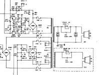
They are on the power supply before the bridge rectifier (see below).
As I understand it the switch chooses different secondary voltages depending on 4 ohm or 8 ohm speakers. Seems odd but I'm no expert!
Mine are the correct "T" type, it is just that I have a packet of 4 amp ones to hand and no easy supply of 5 amp!
Attachments
Last edited:
OK, when it has been on for half an hour (the heatsink is gently warm) I am measuring 11 mV on the left hand speaker outputs and 12 mV on the right.
It that worth attempting to adjust or are the cheap and nasty presets that haven't been moved for 20 years best left alone?
Visually the two presets for each channel are in similar positions so I assume the transistor must have been making a reasonable connection when they were factory set?
Thanks again.
Last edited:
11mV and 12mV offset is fine. I'd leave it alone.
However, are you sure the trimmers are not for adjusting the bias current?
However, are you sure the trimmers are not for adjusting the bias current?
Thanks11mV and 12mV offset is fine. I'd leave it alone.
However, are you sure the trimmers are not for adjusting the bias current?
V401 and V402 are for adjusting the centre voltage as I read it. See the photo I posted in my second post.
Lets say 4 amp will be OK... and qualify that by saying that they are underated if you drive the amp to its max power output into 4 ohm loads. T = time delay so that's fine.
Lets say 4 amp will be OK... and qualify that by saying that they are underated if you drive the amp to its max power output into 4 ohm loads. T = time delay so that's fine.
Thanks....
Given that the centre / ofset voltages are well within the quoted tolerances, the heatsink only gets very gently warm and seems even for both channels plus it sounds fine do you think it is worth hunting these linkages and playing with the current settings?
I'm always bothered that my 10 quid meter may not be that accurate and that it is difficult to get reliable enough probe connections. Plus the presets look real junk, nothing like the quality of the ones in my Arcam amp.
Shall I attempt it or leave well alone?
I'm tempted to say leave well alone... but its your call 🙂
Even if you tweak the adjustments, its guaranteed that there will be no change in sound quality.
Its up to you really.
Even if you tweak the adjustments, its guaranteed that there will be no change in sound quality.
Its up to you really.
I really wouldnt bother messing with the offset pots. Those offsets are low enough already. I'd check bias and consider adjusting that, but if they're really crappy looking trimpots i'd replace them first.
Thanks Guys
I'll probably check them at the weekend. Given the naff pots I won't touch them unless it is far enough out to justify.
The manual says 30 mV across the resistor. Presumably a bit below would be acceptable but not much above? How much would you accept before going to the hassle of fitting new pots etc?
Measure and record the voltages first, from cold through to warmed up. Remember the adjustment is finally made with it at normal temperature.
Anything from 20 mv or so up to say 35mv when its hot is acceptable. You'll probably be surprised just how much the readings change with temperature anyway and just how difficult it might to get a steady 30 mv. It depends how good the amp and physical location of the vbe multiplier is (that middle transistor on the heatsink which is supposedly at the same temp as the outputs). There's a huge amount of thermal lag there so adjust slowly and wait and let it settle.
Anything from 20 mv or so up to say 35mv when its hot is acceptable. You'll probably be surprised just how much the readings change with temperature anyway and just how difficult it might to get a steady 30 mv. It depends how good the amp and physical location of the vbe multiplier is (that middle transistor on the heatsink which is supposedly at the same temp as the outputs). There's a huge amount of thermal lag there so adjust slowly and wait and let it settle.
Yeah it doesnt have to be bang on 30mV. Most of the time this is not determined in any way apart from the designer thinking "20mA of bias, that'll do" 🙂
Ah, NAD with their crazy class G amps. I've never liked that they don't use emitter resistors...
Ah, NAD with their crazy class G amps. I've never liked that they don't use emitter resistors...
Thanks guys, I found how to adjust views on my 3240pe by reading through your posts... I didn't get the solder post bit either. And my amp is horribly soldered also... Rotel looks beautiful compared to it!
- Status
- Not open for further replies.
- Home
- Amplifiers
- Solid State
- NAD 7240PE Questions