Hi experts!
Being a novis in amplifier repairs I just have to say this forum is absolutely fantastic! This is my first post ever but I have spent numerous hours to try and learn from the best. Last year I built an F6. That was so much fun and I learned a lot. Anyway, i’ve been working on an old Nad 705 amplifier that has DC voltage on the left channel and this causes the amplifier to go into protective mode and the speaker relays to open.
Right channel is ok.
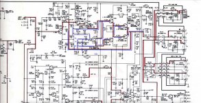
I have tried to illustrate the situation on the schematic of the left channel. The blue lines indicates +8.9v to +10v. On the other channel the voltages are as the schematic shows. Between +1.2v and -1v
Is there someone that have the knowledge to point me in a direction to where the DC is coming from I would be so thankful since I’m running out of options over here 🙂
I have tested all transistors Q101,Q103,Q105,Q107,Q109,Q111,Q113,Q115 with a multimeter and a "T7 Multi function tester". Tested all resistors in this area and checked the caps for shortages (in circuit)
I have replaced C123 just to be sure.
No visual indications of heat or other distress on PCB or components.
Should i maybe replace all electrolytic caps?
Enclosing the service manual for the 705 for reference
I also found this thread from 2020 explaining almost the exact issue I have just with little higher dc voltage.
https://www.diyaudio.com/community/threads/nad-705-in-protection.356159/
I am using a light bulb current limiter when taking voltage measurements
Best regards,
Daniel E
Being a novis in amplifier repairs I just have to say this forum is absolutely fantastic! This is my first post ever but I have spent numerous hours to try and learn from the best. Last year I built an F6. That was so much fun and I learned a lot. Anyway, i’ve been working on an old Nad 705 amplifier that has DC voltage on the left channel and this causes the amplifier to go into protective mode and the speaker relays to open.
Right channel is ok.
I have tried to illustrate the situation on the schematic of the left channel. The blue lines indicates +8.9v to +10v. On the other channel the voltages are as the schematic shows. Between +1.2v and -1v
Is there someone that have the knowledge to point me in a direction to where the DC is coming from I would be so thankful since I’m running out of options over here 🙂
I have tested all transistors Q101,Q103,Q105,Q107,Q109,Q111,Q113,Q115 with a multimeter and a "T7 Multi function tester". Tested all resistors in this area and checked the caps for shortages (in circuit)
I have replaced C123 just to be sure.
No visual indications of heat or other distress on PCB or components.
Should i maybe replace all electrolytic caps?
Enclosing the service manual for the 705 for reference
I also found this thread from 2020 explaining almost the exact issue I have just with little higher dc voltage.
https://www.diyaudio.com/community/threads/nad-705-in-protection.356159/
I am using a light bulb current limiter when taking voltage measurements
Best regards,
Daniel E
Attachments
Hi Daniel,
Disclaimer: I'm working from the schematic and service manual and have no first-hand experience with this amp.
If understand correctly, right channel is active and working, but left channel shows +9V at one end of R121 and +0.7V at the other end? I presume the amp output does not respond to SFR101 adjustment?
There seems to be abnormally high current through R121. Check voltage across R119; there should be no DC voltage across it, suggesting all R121 current is flowing through Q101. Assuming this is confirmed, would you report all voltages at Q101 terminals and voltage at top of bias resistor R105? Thanks.
Hi BSST
wow, thank you for pointing me in the right direction!
R119 had -1.1v across it. R105 had +1.3v and -0.7v on each side. -0.7v on the base of q101 meant that it was off. I adjusted it with SFR101 up to +0.8v then measured R119 again. It was still a bit off but much better. I kept meassureing over R119 and adjusted SFR101 so that it was 0v and BOOM, there it was. The wonderful sound of the speaker relay clicking 😊 the problem now was to keep it at zero because it was very unstable. Desoldered C111 and it was dead. A new cap installed and speaker relays are now stable!
At my beginners level I focused on the wrong things. Wasn’t thinking an incorrect bias voltage could result in what I have been seeing but now I know better. Don't look for a big problem before you rule out all the more probable causes 🙂 Thanks again!
Playing music to Main in works great. And the scope tells me everything looks fine.
Next challenge is the pre amp. It doesn’t amplify the signal. If I connect pre-out to main in and turn the volume to max I can hear the music. sweet music, no distortion but very low volume. same on both channels.
this is such an adventure
/Daniel
Hello again, so the preamp is fine. it was the mute function that could not be switched off without the remote (that I dont have) For now, I lifted the resistors R79 and R80 that fed the base on the transistors controlling the mute function on each channel.
Now on to more challenges
The power output offset is a bit all over the place. Especially on the left channel. From cold it often starts at 200mV and then starts dropping as the amp get warm (i guess) the pot is super sensitive. Im trying ti set it to as close as possible to 25mV Is there anything I can do to fix this?
The current adjustment is to be set to 4.4mV per channel according to the manual. Is this right as the right ch is set to 4.4 but the left is at -4.4mV (I can not set it to a positive value)
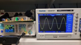
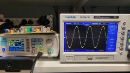
Finally I tested the max output of each channel and noticed that the left ch is a bit off. I am feeding a sine wave to "main in" to bypass the preamp. I can bump it to 4.5v before I see deformation on the right channel. Then if i fed the same signal to the left channel I get different readings.
Could this be due to the fact that I had to replace the power transistors on the left channel with new ones from digikey that werent as closely matched as the original ones on the right channel? (2SA1386/2SC35129) Or could this be due to something else that that you can think of?
OR is the current adjustment and the max power output problem related come to think of it? 😊 😊
Sorry for all the open questions. I would be so thankful for any input
Now on to more challenges
The power output offset is a bit all over the place. Especially on the left channel. From cold it often starts at 200mV and then starts dropping as the amp get warm (i guess) the pot is super sensitive. Im trying ti set it to as close as possible to 25mV Is there anything I can do to fix this?
The current adjustment is to be set to 4.4mV per channel according to the manual. Is this right as the right ch is set to 4.4 but the left is at -4.4mV (I can not set it to a positive value)
Finally I tested the max output of each channel and noticed that the left ch is a bit off. I am feeding a sine wave to "main in" to bypass the preamp. I can bump it to 4.5v before I see deformation on the right channel. Then if i fed the same signal to the left channel I get different readings.
Could this be due to the fact that I had to replace the power transistors on the left channel with new ones from digikey that werent as closely matched as the original ones on the right channel? (2SA1386/2SC35129) Or could this be due to something else that that you can think of?
OR is the current adjustment and the max power output problem related come to think of it? 😊 😊
Sorry for all the open questions. I would be so thankful for any input
Attachments
Hello again, so the preamp is fine. it was the mute function that could not be switched off without the remote (that I dont have) For now, I lifted the resistors R79 and R80 that fed the base on the transistors controlling the mute function on each channel.
Now on to more challenges
The power output offset is a bit all over the place. Especially on the left channel. From cold it often starts at 200mV and then starts dropping as the amp get warm (i guess) the pot is super sensitive. Im trying ti set it to as close as possible to 25mV Is there anything I can do to fix this?
Is the left channel offset more "twitchy" than the right? There should be no DC voltage across R119 since C109//C111 should block DC current flow. If either of these caps were shorted/leaky, offset adjustment pot would be very touchy.
The current adjustment is to be set to 4.4mV per channel according to the manual. Is this right as the right ch is set to 4.4 but the left is at -4.4mV (I can not set it to a positive value)
When you measure/adjust the bias current, you're monitoring the voltage across R143 (R144). If you ensure the voltmeter positive probe is consistently on the supply rail, you'll get positive voltages. These currents cannot go negative.
Finally I tested the max output of each channel and noticed that the left ch is a bit off. I am feeding a sine wave to "main in" to bypass the preamp. I can bump it to 4.5v before I see deformation on the right channel. Then if i fed the same signal to the left channel I get different readings.
Could this be due to the fact that I had to replace the power transistors on the left channel with new ones from digikey that werent as closely matched as the original ones on the right channel? (2SA1386/2SC35129) Or could this be due to something else that that you can think of?
OR is the current adjustment and the max power output problem related come to think of it? 😊 😊
I note the the scope shows the left channel is driven more heavily into clipping than the right. I suspect the gain of the left channel is a bit higher than the right. Try reducing drive about 25% so that both channels show clean sine waves and compare voltage gains. I think you'll find left channel gain is serveral percent higher. The gain of the left amp stage is (1+R121/R119). Resistor tolerances between channels are the likely explanation. If you test each channel's clipping behavior (ignoring the difference in applied generator drive), you'll probably see very similar results.
Regards,
Steve
Thank you for all advice and input!
All the above turned out to be Q101! I measured the right cannel and voltages was as the schematic but something was off with all values around Q101 in the left channel. It tested OK but I replaced it with a KSC1845. Suddenly the offset and current was stable and could be adjusted to desired levels and the amplified curves in the pictures above were the same. and the sound sounds the way it's suppose to. What a learning experience 😀
Thanks
/Daniel
Well done !
I bought in a 1980's Maplin 225WRMS disco amplifier off ebay.
It worked but was very distorted.
I checked all components and they checked out fine.
Transistors all buzzed out as back to back diodes OK.
I kept going back to one point in the circuit which didn't seem right voltages but transistor buzzed out ok and so did surrounding components.
It then hit me that while transistor buzzed out ok it was in fact buzzing out backwards !
It had no number on the transistor which didnt help.
So replaced it with a similar transistor to one in parts list I had in stock and it then worked ok.
It appears someone had been in before me trying to fix it and had replaced NPN with a PNP transistor !
Its hard enough to trouble shoot with correct components in never mind wrong ones.
I built up a set of amplifiers.
None of them worked.
So started from scratch testing all components.
One of the resistors was wrong value.
So got bag out and checked resistance of resistor in it and it didnt match value on the bag.
Farnell had let me down.
I had to remove the wrong resistors from all the pcb's and replace them when replacements came in.
- Home
- Amplifiers
- Solid State
- NAD 705 with DC voltage on one channel