My thoughts also on this rather weird issue. OTOH, is the -24V rail really present, i.e. can you measure -24V at Q707's and it's sibling's in the other channel collectors?
Best regards!
Q707 READINGS
C - -23.84v
E - +23.84v
B - amp goes into protect
Q708 READINGS
C - -23.84v
E - +23.84v
B - +23.84v
Q707 READINGS
C - -23.84v
E - +23.84v
B - amp goes into protect
Q708 READINGS
C - -23.84v
E - +23.84v
B - +23.84v
I'd like to add - if i start the amp with the probe already on the base of Q707, i'm able to measure it as it climbs to 24v. However, it gets to around 21v, and a loud scratchy electrical noise begins to fade in aggressively, which gets very loud and then the amp goes into protect.
Those voltage readings are amiss. The emitter of each should have near zero volts.
Try measuring the voltage from the ground you are using now for your measurements to other known ground points in that area, for example the lower end of R701. This zero volt ground point is crucial for the biasing of that stage.
Try measuring the voltage from the ground you are using now for your measurements to other known ground points in that area, for example the lower end of R701. This zero volt ground point is crucial for the biasing of that stage.
Those voltage readings are amiss. The emitter of each should have near zero volts.
Try measuring the voltage from the ground you are using now for your measurements to other known ground points in that area, for example the lower end of R701. This zero volt ground point is crucial for the biasing of that stage.
Yep - you're right, something very strange going on here. Ground side of R701 to chassis ground measures around 7v, it also does that weird thing i've found in other places, of rising to 20v if i dont touch it, which coincides with the sound fading out. If i touch it, the sound comes back straight away and the voltage gradually drops to 7v again.
I'd like to refer you to something I said here...
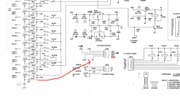
The ground is a weird one. The chassis ground is intact at all points, and it has 0ohm to the chassis ground spade terminal from the power supply. However, if I refer you to J605 on this same schematic page, there’s some strange stuff going on. The schematic claims that 2,4,6 & 8 on the connector should all be connected and are all floating ground rails. 11 is a separate ground which is connected to the same 0v line that the chassis is connected to.
In actual fact, I am observing that 2, 8 & 11 are directly connected, reading 0ohms. 4&6 are connected to each other, but not the others. This might be a clue to what the problem is, but also suggests that the schematic is inaccurate because according to that, 2,4,6&8 should all be connected, and NONE Of them connected to 11 - the chassis ground.
I can observe by looking at the physical traces on the board that the ground side of r701 terminates at 6 on J605, which, as mentioned above is not connected to the chassis ground. The schematic is extremely misleading.
IMPORTANT: It seems that if i disconnect the 'Tone Control & Headphone Amplifier' board from the circuit, by unplugging J605 - the weird ground issues disappear. Once unplugged, i get no voltage on pin 6 on the flex (ground point normally connected to R701). Furthermore, the weird problems of the amp going into protect while probing also stop happening. The problem must be somewhere in the tone control board.
Last edited by a moderator:
I see the NAD 319 has a tone defeat button on it does it make any difference if that is pushed in?
Fraid not

Try and be logical and trace the ground connection of R701 back toward the power supply. That is something definite to work on.
This fault is looking like cracked or damaged print somewhere or possible poor crimping (if that's how its done) in any of the connections.
Thanks for this!
Please correct me if i’m wrong, but my understanding of the schematic is that the ground of r701 is intentionally a floating ground and from the schematic, doesn’t connect to the power supply at all. Also - since unplugging the time board seems to fix all the weird ground issues, it really seems to me like the problem is in this board, and not the power supply? Further to that point - the power amp works perfectly when isolated from the preamp, which also makes me rule out the power supply?
To try and answer as best as possible...
As far as measuring ground continuity between various points in the circuit, all should be tied together. This means that R701 should definitely have direct continuity back to the main power supply ground.
There will be a unique grounding scheme in operation to avoid ground loops, but as far as you are concerned and as far as measurement goes, all should connect together.
I would begin by confirming that outer part of the RCA input sockets measures zero ohms back to the power supply 0 volt line. That line is the junction of the big reservoir caps. Have the amp OFF for all resistance checks.
There should also be no voltage difference between these points when the amp is on.
If that's OK then repeat the test but this time measure to R701. It should be the same, zero ohms and no voltage difference.
There are various ground symbols in use that mean very specific things. I would assume that the chassis connects directly to the main 0 volt line of the power supply but how and where it does so is a design choice.
The Grounding Symbols | In Compliance Magazine
You will often see in equipment references to 'Audio ground', Power supply ground', Digital ground' and so on. All these points have a definite (by design) route back to the main power supply ground and all would read as connected together on a meter. It done that way to avoid interaction.
To try and answer as best as possible...
As far as measuring ground continuity between various points in the circuit, all should be tied together. This means that R701 should definitely have direct continuity back to the main power supply ground.
There will be a unique grounding scheme in operation to avoid ground loops, but as far as you are concerned and as far as measurement goes, all should connect together.
I would begin by confirming that outer part of the RCA input sockets measures zero ohms back to the power supply 0 volt line. That line is the junction of the big reservoir caps. Have the amp OFF for all resistance checks.
There should also be no voltage difference between these points when the amp is on.
If that's OK then repeat the test but this time measure to R701. It should be the same, zero ohms and no voltage difference.
There are various ground symbols in use that mean very specific things. I would assume that the chassis connects directly to the main 0 volt line of the power supply but how and where it does so is a design choice.
Thanks so much for this, i really appreciate your continued help.
The outer ring of the RCA sockets of the pre-out and power-in are connected to the chassis ground, and connected to the 0v line on the power supply. However, the outer ring of the RCA inputs is not connected to this ground, though they are connected to each other, and connected to R701. I understand what you're saying, but I cannot see on the schematic or on the boards themselves how these two grounds are supposed to connect. There are two chassis spade terminals for ground, both of which are tightly screwed and providing a solid link to the 0v line and the chassis.
The sound fading out issue that this amplifier has, has been present since the fault began.
Some additional info for you...
The issue with this amp was caused by the following... someone pulled the speaker cable out of the speaker it was connected to, while the amp was on and playing music. They then pulled that live speaker cable through the mass of cables at the back of their setup, and they *think* the ends of the cable went into or around the CD RCA input sockets. After doing this, they described that there was a pop and the amp let out a very loud hum and went into protect. Since that happened, the amp has had the symptoms described in this thread. The amp has never been opened up prior to this.
When we fixed the positive rail, the loud turn-on hum stopped happening, but the sound fade out thing remains.
The input RCA's should definitely connect back to the PSU via the route shown here.
Based on what you say happened got me wondering whether there is a 'ground lift' resistor fitted that is not shown on the diagram. That could be a typical afterthought/modification introduced in production.
Trace the route with your meter and see where continuity fails. Any such resistor would only be an ohm or two.
Attachments
The input RCA's should definitely connect back to the PSU via the route shown here.
Based on what you say happened got me wondering whether there is a 'ground lift' resistor fitted that is not shown on the diagram. That could be a typical afterthought/modification introduced in production.
Trace the route with your meter and see where continuity fails. Any such resistor would only be an ohm or two.
Yes, after posting that i spotted that on the schematic - i've been looking for just this right now. It's so bizarre, I've studied the underside of this board and the only thing i can spot that the input RCAs connect to is C617. I wonder if the ground lift resistor is on the tone or volume boards... I'll keep looking
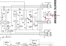
First just try measuring from the RCA's to J505 on the input board. Make sure that is OK. Next make sure there is continuity from J505 pin 4 back to the other end of connection on the PSU and so on.
There is no connection from the input RCAs to J505, there's also no obvious printed line, or resistor connecting them. The output RCAs are connected to J505 though, which i can see physically looking at the board. Can confirm that pin4 of J505 is properly grounded at the PSU.
@ Passmore i re-read through this post and was looking to see if you may have checked R701 in or out of circuit and or replaced it i don't see that mentioned.
In a previous comment you wrote:Ground side of R701 to chassis ground measures around 7v
R701 (as is R702 if i am looking in the correct place) is a metal film 220k resistor 1% i beleive if i am seeing it correctly on the schematic and it is connected to a earth ground per Mooly's article
The one bad metal film resistor on my NAD 216 would sometimes if moved would read correctly and then not like there was a broke connection inside of the resistor like if it was conducting/touching and at other times not. and then after movement (testing and retesting it ) it went completely open. it was taking my amp in and out of protect mode.
After looking at the schematic i was also curious about the input board
Last edited:
@ Passmore i re-read through this post and was looking to see if you may have checked R701 in or out of circuit and or replaced it i don't see that mentioned.
In a previous comment you wrote:Ground side of R701 to chassis ground measures around 7v
R701 is a metal film 220k resistor 1% i beleive if i am seeing it correctly on the schematic and it is connected to a earth ground per Mooly's article
The one bad metal film resistor on my NAD 216 would sometimes if moved would read correctly and then not like there was a broke connection inside of the resistor like if it was sometimes touching and at other times not. and then after movement (testing and restain it ) it went completely open. it was taking my amp in and out of protect mode.
Hey dude, Thanks for this.
R701 and R702 both seem to be solid and measuring 220k in circuit, but I will gladly replace them. However, even if they do need replaced, the GROUND side of these resistors is currently not connected to the 0v ground of the power supply, which Mooly has pointed out that it should be. Currently I'm trying to find where on earth (pardon the pun) it makes this connection, and why that connection is broken.
Last edited by a moderator:
Faults like this are good aren't they
Trace the RCA connection to the board and be sure it reads OK. Then you are going to have to look at the board and physically trace this RCA connection point through the print and back to J505. You are going to have to look closely though.
Trace the RCA connection to the board and be sure it reads OK. Then you are going to have to look at the board and physically trace this RCA connection point through the print and back to J505. You are going to have to look closely though.
I'll have to leave it for just now but try and see if J505 here connects to the common 0V line on this board. The regs at the left would be a good place to check to.
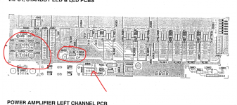
The transistor I circled looks like a relay driver (and if so nothing to do with the fault) but I couldn't just spot it on the circuit diagram I have.
The transistor I circled looks like a relay driver (and if so nothing to do with the fault) but I couldn't just spot it on the circuit diagram I have.
Attachments
- Status
- This old topic is closed. If you want to reopen this topic, contact a moderator using the "Report Post" button.
- Home
- Amplifiers
- Solid State
- NAD 319 Repair