Connect a signal generator to one of the amp's input and trace the signal, step by step, with an oscilloscope. The faulty stage won't show the signal at it's output.
Sorry, without having the service manual before me, it's difficult to give detailled hints. Do you have it? If so, can you check all voltages given there in your amp?
Best regards!
Sorry, without having the service manual before me, it's difficult to give detailled hints. Do you have it? If so, can you check all voltages given there in your amp?
Best regards!
There you are! All voltages appear to be present, as far as i can tell. Yeah, i've been playing around with scope and signal, just haven't found it yet.
Dropbox - nad_319_sm copy.pdf
Dropbox - nad_319_sm copy.pdf
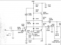
As also the headphone signal fades, and as this fading is in a distorted manner, which excludes the motorized volume control Potentiometer as a possible cause, you'll have to concentrate at the Tone Control & Headphone Amplifier section, shown at p.16. Are both the +24V and -24V rails present?
Best regards!
Best regards!
As also the headphone signal fades, and as this fading is in a distorted manner, which excludes the motorized volume control Potentiometer as a possible cause, you'll have to concentrate at the Tone Control & Headphone Amplifier section, shown at p.16. Are both the +24V and -24V rails present?
Best regards!
The motorised volume control controls the headphone volume too, so does it definitely exclude it?
Yes - 24v+/= are both present on all three boards
I'll look at the circuit when I have a bit more time but initial thoughts would be a shift in DC conditions, and as it affects both channels it has to be something common to both such as a supply, auxiliary supply or bias voltage.
I would look at the DC voltage on the audio output of each stage and see if anything shows up. Pick the stage that drives the power amp and work from that forward toward the inputs. Look for DC shift that follows the fault.
I need to look at the circuit.... does it use a (Toshiba maybe) input/switching selector chip. They were often trouble generally.
I'll look at the circuit when I have a bit more time but initial thoughts would be a shift in DC conditions, and as it affects both channels it has to be something common to both such as a supply, auxiliary supply or bias voltage.
I would look at the DC voltage on the audio output of each stage and see if anything shows up. Pick the stage that drives the power amp and work from that forward toward the inputs. Look for DC shift that follows the fault.
Ok - on it boss.
I need to look at the circuit.... does it use a (Toshiba maybe) input/switching selector chip. They were often trouble generally.
Not toshiba, it uses two of these 4094s. IC802 & IC803
MC14094BCP ON Semiconductor | Mouser United Kingdom
Dropbox - Screen Shot 2018-12-11 at 15.31.16.png
Last edited by a moderator:
The motorised volume control controls the headphone volume too, so does it definitely exclude it?
As you said the fading shows some distortion, yes!
OTOH you can easily distinguish an operating potentiometer motor, I think.
Best regards!
I'll look at the circuit when I have a bit more time but initial thoughts would be a shift in DC conditions, and as it affects both channels it has to be something common to both such as a supply, auxiliary supply or bias voltage.
I would look at the DC voltage on the audio output of each stage and see if anything shows up. Pick the stage that drives the power amp and work from that forward toward the inputs. Look for DC shift that follows the fault.
I just checked this - basically no dc on outputs of preamp into poweramp, it measures 0.007vdc which increases to 0.017vdc over 15 seconds of it being on.
There's some really strange stuff going on...
If i probe IL or IR on J602 with the scope, the amp immediately goes into protect until i take the probe away.
If i check dc voltage on IL or IL with meter, the amp shows 20vdc, which gradually goes down to 7v. if i take the probe away, the sound does its usual fade out to crackle thing. If i then touch IL or IR again once the sound has faded away to nothing, it suddenly comes back, and goes to 20v again, which once again starts fading.
Before you ask - NO the meter doesn't have its probe plugged into the current test socket and YES the scope is grounded correctly
Last edited by a moderator:
IL and IR are the volume potentiometer's hot ends. There are only passive components before them. Do these strange DC measurements change when you turn the volume up and down?
Best regards!
Nope, the volume pot has no affect on them.
Just from quickly looking at the circuit and I think I would begin by seeing if the audio remains clean at the inputs to the tone stage buffer, that's the inputs to Q701 and Q702.
Also look at the output of the buffer on the positive ends of C715 and C718. Does any DC shift occur here and does the signal fade at that point.
Also look at the output of the buffer on the positive ends of C715 and C718. Does any DC shift occur here and does the signal fade at that point.
Just from quickly looking at the circuit and I think I would begin by seeing if the audio remains clean at the inputs to the tone stage buffer, that's the inputs to Q701 and Q702.
Also look at the output of the buffer on the positive ends of C715 and C718. Does any DC shift occur here and does the signal fade at that point.
Struggling to discover much just now... touching the inputs to Q701 and 702 with either scope or meter causes a loud noise and the amp to go into protect. It then comes out of protect a few seconds later.
The output on positive ends of C715 and C718 seems fine - they both just sit at 23.5v, no change with the fadeout.
I've noticed all kinds of weird things going on, when probing certain components the amp goes into protect. Sometimes the sound comes back, or the hum.
Hmmm... that all sounds a bit odd tbh.
I would have expected the positive end of C715 to be close to zero volts DC. That needs looking at.
Check your measurement points and grounds. Make sure there isn't a floating ground anywhere.
Touching the input shouldn't send it crazy, at least I'm surprised if it does. Checking at the junction of R701/703 and C701 and it definitely shouldn't upset it.
Lets resolve the odd DC reading first.
Hmmm... that all sounds a bit odd tbh.
I would have expected the positive end of C715 to be close to zero volts DC. That needs looking at.
Check your measurement points and grounds. Make sure there isn't a floating ground anywhere.
Touching the input shouldn't send it crazy, at least I'm surprised if it does. Checking at the junction of R701/703 and C701 and it definitely shouldn't upset it.
Lets resolve the odd DC reading first.
Okay, I’ve triple checked C715 and it definitely seems to have 23.84v on positive and 0.005v on negative.
If I use my meter to check the junction of R701/703 and c701, i get a reading of 20v which gradually drains down to around 7v. If I take the probe off this point, it seems to go back up to 20v which can be observed as soon as I probe it again, at which point it drains once again. The sound also comes back as soon as I probe this point, and drains a few seconds after I take the probe off it. If I use the scope on the point with the probe set at 10x - i can’t see my 1k sine at all, just a noisy line. If I switch the scope to 1x and probe the point, the amp goes into protect.
The ground is a weird one. The chassis ground is intact at all points, and it has 0ohm to the chassis ground spade terminal from the power supply. However, if I refer you to J605 on this same schematic page, there’s some strange stuff going on. The schematic claims that 2,4,6 & 8 on the connector should all be connected and are all floating ground rails. 11 is a separate ground which is connected to the same 0v line that the chassis is connected to.
In actual fact, I am observing that 2, 8 & 11 are directly connected, reading 0ohms. 4&6 are connected to each other, but not the others. This might be a clue to what the problem is, but also suggests that the schematic is inaccurate because according to that, 2,4,6&8 should all be connected, and NONE Of them connected to 11 - the chassis ground.
@ Passmore when i was troubleshooting my NAD 216 i had chassis ground and then i had none i found that i had to remove the power supply PCB and clean the one and only PCB to chassis ground screw area under the PCB then after that i had chassis ground it was causing all sorts of weird/odd readings afterwords my voltage measurements were stable just a thought.your issues may or may not be a ground issue but it kinda sounds like one to me.
Last edited:
^ I'd definitely check out what Sqeek mentions. This really is one of those things that you need in front of you.
The above part of the circuit I posted should have all those ground points at zero volts (power supply ground) and the voltage on C715 should be close to zero, not 24 volts.
Try measuring from power supply ground (junction of the main reservoir caps in the power supply). Whether and how that point connects to the chassis is something you will need to investigate.
@ Passmore when i was troubleshooting my NAD 216 i had chassis ground and then i had none i found that i had to remove the power supply PCB and clean the one and only PCB to chassis ground screw area under the PCB then after that i had chassis ground it was causing all sorts of weird/odd readings afterwords my voltage measurements were stable just a thought.your issues may or may not be a ground issue but it kinda sounds like one to me.
^ I'd definitely check out what Sqeek mentions. This really is one of those things that you need in front of you.
The above part of the circuit I posted should have all those ground points at zero volts (power supply ground) and the voltage on C715 should be close to zero, not 24 volts.
Try measuring from power supply ground (junction of the main reservoir caps in the power supply). Whether and how that point connects to the chassis is something you will need to investigate.
Hey Sqeek, thanks a lot for this!
I totally agree it sounds like a ground issue, but I'm pretty sure it's not that one - I've checked the chassis ground over several times and the resistance is always 0ohms solidly.
Hey Mooly, thank you for your continued help!
Let me clarify this. The 0v rail in the power supply is not directly connected to the chassis ground, by design. It is connected to C233, the other side of which is connected directly to the chassis, by a wire with a spade terminal and screw, which screws the pcb down at the same time. I can confirm that the connection from ground (chassis) to C233 is absolutely sound, and can confirm that the other end of C233 is connected to the 0v rail & AC0 on transformer. I presume C233 is essentially acting as a low-pass filter here. Oddly - if i test resistance between the 0v line and the chassis, i get 0ohms. I have checked C233 out of circuit and it is not shorted, so not sure what the explanation to that is. I've checked on the left and right power amplifiers on the schematic and they also have this 0v line connected indirectly to the chassis through low-pass capacitors - perhaps one of them is shorted? Does that hypothesis make any sense to you, is it worth checking out? From my understanding of the schematic, i should not see 0ohms between the 0v star point ground and the chassis - please correct me if i'm wrong.
To be clear guys, this problem of the sound cutting in and out, hums and hisses etc was all happening before taking it apart. When the problem first appeared, I probed around before removing anything and it was doing all the same stuff. (At the time it also had the loud hum and 100+v line though, which we've fixed.).
- Status
- This old topic is closed. If you want to reopen this topic, contact a moderator using the "Report Post" button.
- Home
- Amplifiers
- Solid State
- NAD 319 Repair