the service manual states the MJ15003/4 units and the one I am working on has these- The original mounting uses hollow ceramic posts covering the B/E pins of the transistors, with small connecting wires soldered onto them
mine has 2sa1095 and 2sc 2565's fitted
actualy that picture was just of one off the net, i hannt taken the bottom off of mine at the time
just about to start on it tonight(if the rum dont come out first tonight )😀 its been quite a week and i need one!!!
actualy that picture was just of one off the net, i hannt taken the bottom off of mine at the time
just about to start on it tonight(if the rum dont come out first tonight )😀 its been quite a week and i need one!!!
Attachments
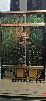
Interesting…. That type of heat sink is usually associated with derives like those Toshiba flat packs. But having the holes drilled for TO-3s suggest that someone gave thought to being able to use either type. What’s more inconsistent is that the 15003/4 are just run of the mill low speed devices and those particular Toshiba types happen to be a special *very* high speed type (80 MHz fT). It might be hard to make the same circuit work (well) over that much variation. One would expect the alternate types to be closer to each other. At the time, Sanken did make LAPTs in TO-3, and more common 20 MHz flat packs could have been chosen if 4MHz devices work. That does make on wonder what the designers were thinking.
@wg_ski- completely agree- the later NADS used the same heatsink configuration with "flat" transistors.
Without wishing to hijack this thread- the L/R input buffers Q501/503 and Q052/504 -do you think they are unity gain?
the 3140 on my bench is refusing to give output from the preamp
thanks
Without wishing to hijack this thread- the L/R input buffers Q501/503 and Q052/504 -do you think they are unity gain?
the 3140 on my bench is refusing to give output from the preamp
thanks
so update
all fuses removed and both rectifiers out-lamp still glows a bit, so transformer?
cant see what else it can be now, at least this first part
its a bit weird,if the drawings correct, and it may not be D801 is fused before the rectifier and D801 afterwards? well thats the way it looks to me
all fuses removed and both rectifiers out-lamp still glows a bit, so transformer?
cant see what else it can be now, at least this first part
its a bit weird,if the drawings correct, and it may not be D801 is fused before the rectifier and D801 afterwards? well thats the way it looks to me
I doubt there is any problem with the transformer. With fuses 1 through 6 pulled and everything else in place the bulb should not light.
Remember the transformer still draws a little current even with no load to maintain the magnetic field in the core. Its not much but is enough to cause a bulb to glimmer, particularly if it is a 60w one. See what DC voltage you have at fuses 3 to 6 in that state (just one end of the fuseholder will have DC voltage). Remember to discharge the caps gently before refitting fuses.
Remember the transformer still draws a little current even with no load to maintain the magnetic field in the core. Its not much but is enough to cause a bulb to glimmer, particularly if it is a 60w one. See what DC voltage you have at fuses 3 to 6 in that state (just one end of the fuseholder will have DC voltage). Remember to discharge the caps gently before refitting fuses.
your proberbly right as it happens.
2 of the filter caps were totaly dead so i replaced all 4 as the other 2 were down to about 1500uf
im getting 35vac feed from each transformer to the rectifier doides but nothing out.
im only getting about 400mv drop across these, so could this be the issue
im getting no DC at all at the fuses
2 of the filter caps were totaly dead so i replaced all 4 as the other 2 were down to about 1500uf
im getting 35vac feed from each transformer to the rectifier doides but nothing out.
im only getting about 400mv drop across these, so could this be the issue
im getting no DC at all at the fuses
Something sounds amiss there. It is very rare for a rectifier to fail and if they do then it is usually short circuit.
This supply is unfused up to this point. If you have voltage going into the bridge then you should see DC voltage on the caps equal to 1.4 multiplied by the AC value.
Measure the AC into the bridge and and DC out of the bridge from ground.
This supply is unfused up to this point. If you have voltage going into the bridge then you should see DC voltage on the caps equal to 1.4 multiplied by the AC value.
Measure the AC into the bridge and and DC out of the bridge from ground.
Attachments
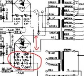
ok so i found this issue, there was a screw missing on the grounding bar so i now have 47v on all 4 fuse sets
and 51v on the other rail
also i replaced C409 as that was broken
update the 2 filter (470uf)caps on the other supply are as dead as a dodo as well and i dont have any of these in any voltage(typical)
could you use any other value? other than 470uf?
quite a few individual things wrong here im guessing
Last edited:
this will have to be work in progress untill i get the parts so ill be moving onto something different in the mean time
OK.
A faulty cap happens... but I would ask whether all these electrolytics really are duff. If you mean C805 and 806 for the 470uF then 220, 330 or 1000uF would all work.
A faulty cap happens... but I would ask whether all these electrolytics really are duff. If you mean C805 and 806 for the 470uF then 220, 330 or 1000uF would all work.
yep i tested them with my esr meter
ok ill try that.im looking at another amp at the moment but having trouble locating the test points they refer to so you can check/ adjust the centre and idle
ok ill try that.im looking at another amp at the moment but having trouble locating the test points they refer to so you can check/ adjust the centre and idle
Right then... 🙂 I'll reserve judgement on those caps 😀 Old but otherwise OK caps could show what looks like high ESR compared to modern new parts. You could see 0.5 ohm or so for that kind of value.
And you are reading them out of circuit?
0uF is kind of pretty conclusive, however 0 ohms is a short and O/L in meter speak usually means 'outside of range' like an ohmeter with the leads floating.
If you connect the cap across a 9 volt battery you should then be able to measure 9 volts on the cap when the battery is removed. If it does that OK and holds the voltage then try a 100k across the cap while measuring the voltage. The voltage should fall to about 2.5 volts after 1 minute.
Try the battery. I'm curious as it would be really weird for all these caps to have failed. If they have then have of course but it's just weird...
tried 3 different meters,new battery in the esr one, even my multi meters which have a capacitance check on them, which i dont realy use TBH as you have to work out the resistance of the leads, but they all said 0uf
strange isnt it.
strange isnt it.
But what happens if you wire the cap to the 9 volt battery? Just put the cap across a battery.
Then remove the cap and measure the voltage across it. The cap should hold the 9 volts.
Then remove the cap and measure the voltage across it. The cap should hold the 9 volts.
Try the battery. I'm curious as it would be really weird for all these caps to have failed. If they have then have of course but it's just weird...
well once again you are quite right, they all, apart from one charged up to 8v
- Home
- Amplifiers
- Solid State
- NAD 3140