Scoping it is a good idea. You can also look for crossover distortion if you turn the bias to zero (if it will go that low). You would need a pure high frequency sine at low amplitude (say 1 volt pk/pk) and an 8 ohm or lower load.
I'm going to have to double check everything, but I'm sure I've done it right. Scope shows nice clean DC at the terninals
Make sure you use a bulb tester at this point.
You need to see the voltage across the vbe multiplier increase to turn the FET's on but remember the FET's need only a couple of hundred millivolts per FET to begin to conduct.

You need to see the voltage across the vbe multiplier increase to turn the FET's on but remember the FET's need only a couple of hundred millivolts per FET to begin to conduct.
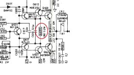
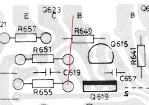
I did wonder.If that resistor is across the gates it will stop the bias voltage developing.
Then it has to be that then. Ill check it out later when i get home👍
Make certain the FET's are connected correctly first of all. Make sure the Source of each FET goes to the output line and make sure the feedback take off point is connected. 15 volt on both the gates suggests a massive DC offset issue as much as anything else.
We know the mods work because we've done them before.
We know the mods work because we've done them before.

Now we have a loud buzz on one channel so I'm gonna have to get the scope out. It gets louder when I touch the case with my hands
That sounds like a missing ground somewhere. Scope will show if it is pure hum/buzz or whether there is something else going on like instability. Could be something like a missing screw maybe grounding some print to the chassis.
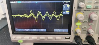
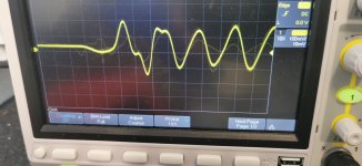
I see the scope saying 11.9kHz in the first image. You need to be sure of the frequency. If that waveform is at high frequency then you have a stability issue..
- Home
- Amplifiers
- Solid State
- NAD 3140 Conversion to lateral FETS