im having trouble adusting the centre voltage on one channel only, which currently sits outside of the specified ranges of 0v +/- 30mv (currently varying up and down between 40mv and 50mv ) so i dont want to leave it.
the idling current is within limits, so thats ok
soft clipping has no infulence, nor does the impedence switch
with the solder short removed the pot is having no influence.
I have spares of these so ive elimintated that as it is perfect 0-1k
when you turn the amp on it works ok, so its a bit tricky tracing this one
ive checked for all the obvious things visualy, but i dont want to start pulling loads of components out unessesarily unless i realy have to as i could do more harm than good.😕
any ideas?
cheers
Attachments
Last edited:
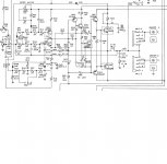
Have you measured the R408,410,412,414,416,418,420 and 436? Also diodes 402 and 404?
These can be done with power off and hopefully without pulling anything apart. A resistor that has gone or a leaky diode could give a variance.if those all check out I would pull Q402, Q404 and check out of circuit specifically their voltage drop and Hfe compared to the data sheet.
These can be done with power off and hopefully without pulling anything apart. A resistor that has gone or a leaky diode could give a variance.if those all check out I would pull Q402, Q404 and check out of circuit specifically their voltage drop and Hfe compared to the data sheet.
I'd be looking for a dry joint or cracked track around one of the components connected to VR402. Have you tried prodding around with a chopstick while you monitor the offset? To test transistors in circuit you can apply heat and see it that changes things. A mini blowtorch like used for heatshrink used carefully can heat a single component at a time. Even better if you have some freezer spray, you can put a drop on each one in turn and see if they change behaviour.
Have you replaced any of the semiconductors in this channel, particularly those in the front half of the circuit (so not outputs and drivers).
How close is the other channel to having zero volt offset with regard to the preset position. In other words is the preset almost at one end even on the good channel?
How close is the other channel to having zero volt offset with regard to the preset position. In other words is the preset almost at one end even on the good channel?
so no components changed at all other than the pot just to make sure it wasnt that, no no solder drys on that
the other channel is ok centre was at @ -18v now at 0 after adjustment and idling @ 28mv respectivly
the other channel is ok centre was at @ -18v now at 0 after adjustment and idling @ 28mv respectivly
The other channel was minus 18v but adjusts OK to zero...
That is one heck of a range of adjustment which in itself doesn't really sound right tbh. I would have expected the preset to just swing it over a few hundred millivolts range at most.
If the channel you are working on hasn't got that same large adjustment swing then I would flip the problem around and suggest the other channel is really the one with a problem... if that makes sense.
Going out to play now 😀
That's more like it 🙂
You might be chasing a non existent problem with a circuit like that. I suspect the DC offset will shift with supply voltage and so if the mains is high or low then the offset may change and/or be more one ended on the preset.
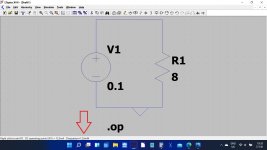
At the end of the day if there is no fault then it is easy to tweak the circuit to give the correct offset with the preset centred. 50 millivolts historically would be considered pretty decent. We used to reckon on -/+ 100 millivolts as being acceptable. If you work the power dissipation that 100 millivolts causes in an 8 ohm load you will see it is a non issue... I'll let you work that one out 😉
You might be chasing a non existent problem with a circuit like that. I suspect the DC offset will shift with supply voltage and so if the mains is high or low then the offset may change and/or be more one ended on the preset.
At the end of the day if there is no fault then it is easy to tweak the circuit to give the correct offset with the preset centred. 50 millivolts historically would be considered pretty decent. We used to reckon on -/+ 100 millivolts as being acceptable. If you work the power dissipation that 100 millivolts causes in an 8 ohm load you will see it is a non issue... I'll let you work that one out 😉
Watts would be voltage squared divided by resistance so (0.1*0.1)/8 would be 0.00125 watt or 1.25 milliwatt.
There are different ways to do it, none of them easy really.
I always tend to use two resistors with a tapping at the centre, so electrically just like a pot. If it is a 100k pot and you want it midway then you make each resistor 50k. If you want it turned up 10% from minimum (for a linear pot) then you make the upper resistor 90k and the lower 10k.
You can set LT to plot more than one run of a simulation on a graph. See post #222 here:
Installing and using LTspice IV (now including LTXVII). From beginner to advanced.
Remember LT has to run the sim for any different value and so you can never have a part you can just alter on the page and see the changes, you have to alter the values and rerun the sim.
You can also create your own symbols for parts like a pot .
Post #4 here is quite interesting. Just click through the missing model error message.
LTSpice Potentiometer?
so im continuing to check through this.after a disasterous start this morning where i took out 2 of the main output transistors by shorting out one of the others by mistake, im now back to sq 1(i guess it doesnt pay to work on anything after a few bevies the night before)
checked all over for dry joints, re flowed a few that looked a bit dodgy.
i have checked some, but not all the resistors and they are ok so far.
anyway so for now i have re shorted the connections across R461 and R462 and what im concerned about is the voltages at the speaker terminals
right channel a and b 0 mv
left channel a and b 256mv
i have also been doing some voltage comparisons at all of the surrounding transistors and there is nothing realy much difference between them.
so clearly something still amis and im getting a bit stuck now so im gonna take a break for a bit
so if any of you guys have any ideas!!
Back at the start you mentioned an offset of around 40 to 50 millivolts but now you say it is 256 millivolts.
That sounds like something has changed following the latest mishap. I'm wondering if you now have two issues rather than one.
With no speaker connected is the idle current still OK on the repaired channel? That is a pretty good check that the output and driver stage is OK.
The midpoint voltage is set by the preset altering the current in 'constant current source' Q402 and it does that by altering the reference voltage developed between the base of the transistor and the positive rail.
You could check and compare the voltages across D402 and D404 with the other channel. Also compare voltage across R436.
all below with solder shorts removed
idle current on the 'faulty' side is -39mv
voltage-ref to ground
D401= 612mv
D403= -34mv(both sides of diode)
R435= -34mv(both sides of resistor)
(across R435 460mv)
voltage-ref to ground
D402=608mv
D404=-34mv(both sides of diode)
R436=-35mv(both sides of resistor)
(across R436 570mv)
idle current on the 'faulty' side is -39mv
voltage-ref to ground
D401= 612mv
D403= -34mv(both sides of diode)
R435= -34mv(both sides of resistor)
(across R435 460mv)
voltage-ref to ground
D402=608mv
D404=-34mv(both sides of diode)
R436=-35mv(both sides of resistor)
(across R436 570mv)
Last edited:
- Home
- Amplifiers
- Solid State
- nad 3130 Centre voltage adjustment issue