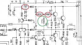
The component in the green circle, is a quad diode in one package.
I don't think they make them anymore. But you can use 4 single diodes in series. It will work exactly the same way.
4x 1N4150 should work fine in this setup. It won't look as clean as the original, but if you can't get the original, it's still better than nothing.
I don't think they make them anymore. But you can use 4 single diodes in series. It will work exactly the same way.
4x 1N4150 should work fine in this setup. It won't look as clean as the original, but if you can't get the original, it's still better than nothing.
as attached@poundy- what is the number on the device?
Attachments
I would link that diode out while you are trying to fix the other faults. Linking it will force a zero bias condition and providing no other faults are present then the amp will work normally.
Only then look at fixing/replacing the diode.
A vbe multiplier as Jaycee suggests is the best option.
Only then look at fixing/replacing the diode.
A vbe multiplier as Jaycee suggests is the best option.
i did replace the diode.so shall i take it out then?
when you say fit a VBE multiplier, is this replacing something or fitting new(does not currently exist)?
when you say fit a VBE multiplier, is this replacing something or fitting new(does not currently exist)?
I would link that diode out while you are trying to fix the other faults. Linking it will force a zero bias condition and providing no other faults are present then the amp will work normally.
Only then look at fixing/replacing the diode.
A vbe multiplier as Jaycee suggests is the best option.
the bias is already close to zero on both channels so i am further confused
i did replace the diode.so shall i take it out then?
when you say fit a VBE multiplier, is this replacing something or fitting new(does not currently exist)?
Its making something to replace the diode string. The economy version is one transistor and one preset. Only worry about doing that when the amp is fixed and playing OK.
Never remove the diode/s as running in that state would destroy the output stage. All shorted out is fine.
the bias is already close to zero on both channels so i am further confused
The 'four diode' bias chain relies a lot on the individual transistor and diode characteristics. If they have been replaced then it may well not work as intended as modern parts have slightly different forward volt drops due to different manufacturing and doping processes.
i didn't say there was a problem with the diode string, i just asked what the symbol represented.🙂
i think we are talking about a different diode, i was referring to D602 that had failed and i replaced.
i think we are talking about a different diode, i was referring to D602 that had failed and i replaced.
Last edited:
think there is a bit of confusion here
both channels centre are at +/-2mv so no problem there now i have replaced :
(as per the PM i sent to you)
main filter caps were almost shot at 2200mf(should be 6800) Q612 was shot,D602(in 2 halves blown),R624,R626 and R628,(all burned out)
so this is where i currently am with it.
i haven't had a chance to check the rest yet but ill report back if i get stuck 🙂 and im sure i might at some point.
Ay, confused 😀
It was this:
I thought you were chasing a low or no bias (bias here means the quiescent current flowing in the output transistors)
Carry on 🙂
It was this:
the bias is already close to zero on both channels so i am further confused
I thought you were chasing a low or no bias (bias here means the quiescent current flowing in the output transistors)
Carry on 🙂
If the output voltage isnt sitting near zero, the bias current in the output stage might not be right. Got to fix that first. If you’re stuck to the negative rail, something is causing Q606 and/or Q608 to go full “on”. Could be shorted, or be the input stage out of whack. Look for open resistors that look perfectly normal too - it happens. Try shorting the base-emitter of Q606 to see what happens. It SHOULD stick to the + rail.
What fault are you trying to fix then?
If the DC offset is OK then the amp should be working. What is not right with it.
If the DC offset is OK then the amp should be working. What is not right with it.
well im not sure i am at the moment.The only reason i quired was that after i had repaired the faulty items, the 4 main output transistors all have very different voltages on the b/e terminals
all of Collectors were of even voltages at around 31v/-31v
i just wouldnt have expected to see 0.560mv on one emitter (npn) Q610 and -31v on the other opposite (npn),Q609 which is why i was going to start looking at where the differences started.
I had already found various components burned out or damaged just by visuals, so i would have been suprised if that was it,as they say.
If they had all been around a simlar levels on both channels i would have assumed it was at least close to being ok.
- Home
- Amplifiers
- Solid State
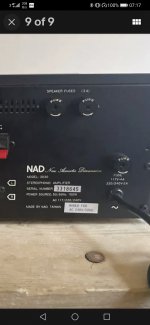
- NAD 3030 in a mess