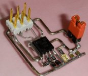
Yes I did. The 3130 there are no spare contacts they are just soldered to the connections with other wires, infavt they are the same switch
I thought it would be like that which means if you want an LED indicator then you would have to add a little circuit to drive the LED.
Here are a couple of doodles. The simple version using a JFET (a small signal junction field effect transistor) would need verifying as it depends critically on the gate/source pinch off voltage. Although it works in simulation it could be critical on the transistor type used. This runs off the 6 volt Zener used to feed the bargraph LED driver.
The opamp version is much more definite. Although a comparator might seem a more obvious choice an opamp usually works just fine here. Get the choice right and it should work with just one rather than two IN4148's. Something like a TL061 (low power) or even a TL071 should be OK. Even a 741. Although many opamps will not swing down to zero the residual voltage should be way below the LED's forward voltage meaning the LED is fully off when needed.
The third version just swaps the LED and opamp inputs around driving the LED toward ground to light it. No worries over the opamp not hitting zero now.
The opamps can be fed from the regulated 30 volt rail.
When the link (switch) is closed the circuit soft clips and the LED lights.
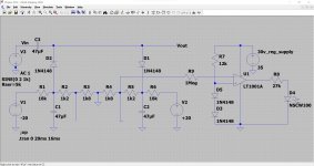
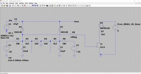
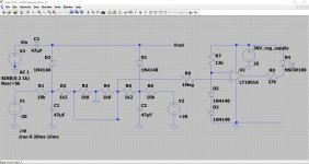
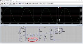


Attachments
what would stop you just connecting to the normaly open side of the switch itself, as on the 3130 the light is only on or off, it isnt triggered by soft clipping, it just is on or off
We found that loosing teh jumpers and replacing with good RCAs and a very short peice of better wire.
dave
dave
what would stop you just connecting to the normaly open side of the switch itself, as on the 3130 the light is only on or off, it isnt triggered by soft clipping, it just is on or off
I would have to see the switch to be sure but the diagram shows a typical double pole double throw (DPDT) switch. I'm assuming it looks like this and both sides are used as per the circuit.
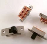
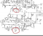
I really can't see any way to do it without adding a bit of circuitry. When the soft clip is on the voltages on the switch fall to zero. All the switch does is alter the voltage on those two diodes and that sets the clip point.
The circuit actually still soft clips the input signal when off but it does so at a point that will be overdriving the amplifier (so the output will now be clipped).
If the JFET circuit is workable in practice then its dead easy to implement. You can solder the transistor Source to the 6 volt Zener and wire the LED and its series resistor to the front panel somewhere. The gate of the FET connects via the 10 meg to the clip circuit.
OK so I'm going to look at doing this, I might need a bit of help, I'll give you a shout if I doI really can't see any way to do it without adding a bit of circuitry. When the soft clip is on the voltages on the switch fall to zero. All the switch does is alter the voltage on those two diodes and that sets the clip point.
The circuit actually still soft clips the input signal when off but it does so at a point that will be overdriving the amplifier (so the output will now be clipped).
If the JFET circuit is workable in practice then its dead easy to implement. You can solder the transistor Source to the 6 volt Zener and wire the LED and its series resistor to the front panel somewhere. The gate of the FET connects via the 10 meg to the clip circuit.
OK. The simple FET version is the one that would need 'proving' for real if that is the version you go for.
For the FET version would help to know the voltages you have for real at these four points and to measure them with the switch in each position. It doesn't matter which channel you use, both are the same and we only use one. Although the diagram shows the voltages and we can calculate them... it is a NAD 😉 and you never know if anything is different to the manual.
So with soft clip off.
A=
B=
C=
D=
And with it on.
A=
B=
C=
D=
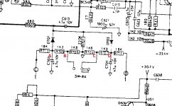

ok im going to have to get another out as the current one doesnt realy have the ability right now 😂
I fail to understand this infatuation with NAD amps, especially the NAD3020 (huge amount fo threads here).
Were they sold is such high quantities than every cellar and attic has at last one or two lying around?
Judging by the schematics and the various simulations I see nothing exceptional.
My Proton AM-20 which seems to be NAD-related is average at best.
Maybe I should build a NAD3020 clone and experience it first person?
Comments welcome.
ok im going to have to get another out as the current one doesnt realy have the ability right now 😂
I've looked again at the simple FET circuit and actually tried it for real and... it is too dependent on FET characteristics. It can be made to work (needs an additional resistor) but on balance it is not great. It is not really good design to have something that depends on being tweaked like that.
The problem is the turn on and turn off voltages (or pinch off as its called for FET's)
Using an opamp looks to be the way to go and it can still be done really easily 🙂
I fail to understand this infatuation with NAD amps, especially the NAD3020 (huge amount fo threads here).
Were they sold is such high quantities than every cellar and attic has at last one or two lying around?
They were massively popular and recommended as the basis for many systems. No idea on numbers but they were a big seller.
'No need to build one. In one guise or another ( they were also combined as receivers, given facelifts and pretty lights etc. then renumbered) but the basic amplifier was the most numerous domestic audio amplifier of all time, globally. You can still buy wrecks or do some "dumpster diving" for them in many countries. At one time I had a stash of about 15 units, mainly for their difficult to source, hometaxial 2N3055s and other bits and pieces needed for repairs.Maybe I should build a NAD3020 clone and experience it first person?
Comments welcome.
Simply though, the popularity lies in the respectable sound quality - nothing else in the price range has approached this level, as your comment on manufacturer Proton's own models might suggest. https://en.wikipedia.org/wiki/NAD_3020
Why don't you listen to one before you pass judgement? A proton Am20 is as you describe average at best,and nothingike any of the early NAD amps, but some of the best hifi guys reviewed these when they were first produced, and a claimed rave reviews. Of course if you spend enough money you will get better, but I've listened to alot of amps over the years and equivelent modern day digital amps don't even Come close, they sound too 'clinical' and 'unreal' with no sound stage, which is precisely why they are becoming popular again. Quite simply, the older kit (IMO), and obviously many others agree with me. I sell most of my amps that I rebuild to guys who 'had one of these years ago' and want one again because the digital ones they have owned since just don't cut the mustardI fail to understand this infatuation with NAD amps, especially the NAD3020 (huge amount fo threads here).
Were they sold is such high quantities than every cellar and attic has at last one or two lying around?
Judging by the schematics and the various simulations I see nothing exceptional.
My Proton AM-20 which seems to be NAD-related is average at best.
Maybe I should build a NAD3020 clone and experience it first person?
Comments welcome.
So the op amp it is then, I just need to work out how it's going to fit, or fit a different switch with a spare pair of ContactsI've looked again at the simple FET circuit and actually tried it for real and... it is too dependent on FET characteristics. It can be made to work (needs an additional resistor) but on balance it is not great. It is not really good design to have something that depends on being tweaked like that.
The problem is the turn on and turn off voltages (or pinch off as its called for FET's)
Using an opamp looks to be the way to go and it can still be done really easily 🙂
They were massively popular and recommended as the basis for many systems. No idea on numbers but they were a big seller.
- Home
- Amplifiers
- Solid State
- NAD 3020 project, strip down and upgrade.
