No, but if the emitter resistors open (R905 ~ 9015 and the others in the same position), it will normally take out the over current protect, Q337.
Check the 4R7 resistors to the bases, and if even one output is blown, change the entire bunch on that channel and also the drivers. Always replace one level beyond the last damaged part you see. The parts may not fail outright, but this will change the specs, like beta and other things. Looks like this one went from "stem to stern", just like Yamaha home amps used to. You also had high current out the input stage, so if this was driven with an op amp, replace that too.
Total meltdown, cool. The fixed channel should be a lot better than new if you match the various transistors as best you can. Matching compliments isn't something I've designed a jig for yet.
You should be testing for junction opens and shorts as well as beta when testing transistors. Don't bother matching Vbe drops, you must match beta.
-Chris
I did check these and all measure within spec <5% variance.No, but if the emitter resistors open (R905 ~ 9015 and the others in the same position), it will normally take out the over current protect, Q337.
Thanks Chris - and Yes, my list is growing pretty fast on parts. Really starting to wonder if this "teaching lesson" will be worth the price when i get done with it. Oh well - it should teach me alot.Check the 4R7 resistors to the bases, and if even one output is blown, change the entire bunch on that channel and also the drivers. Always replace one level beyond the last damaged part you see. The parts may not fail outright, but this will change the specs, like beta and other things. Looks like this one went from "stem to stern", just like Yamaha home amps used to. You also had high current out the input stage, so if this was driven with an op amp, replace that too.
Total meltdown, cool. The fixed channel should be a lot better than new if you match the various transistors as best you can. Matching compliments isn't something I've designed a jig for yet.
You should be testing for junction opens and shorts as well as beta when testing transistors. Don't bother matching Vbe drops, you must match beta.
-Chris
Uh, I'm a bargain hunter and there are bargains out there. I don't do exact match transistors, those are pricey.Really starting to wonder if this "teaching lesson" will be worth the price when i get done with it. Oh well - it should teach me alot.
TO-92 I'm paying $8 a hundred usually. If you don't mind doing things like complementing the MPS8099 npn to the MPSA56 pnp, which I don't.
I use the power polarity and VCE selectors to set min-max on newark, then see what is on sale that day. BC639, BC557, ksa992,ksc1845 were $6 a hundred. MPS8099 were $5.50 MPSA55 were $2.40 a hundred.
I monkey by substituting output transistors, too. I'm not running a bar so the 24 hour power rating doesn't matter much to me. Peak current does, soa does. MJ15024/25 are about $5.50 each, but TO3-PMJ21194/95 are $2 and 2SA1294/2SC3263 were under $1.60 ea.
Drivers, I can hear slow ones (TIP41C/42C) so I pay for the faster ones. MJE15033/34 have recently decreased massively in price from $4 ea to $1.60
Where I pay a premium is electrolytic caps, for long life mostly. I get tired of chaning those out all the time.
This repair hobby is supposed to be fun, not a quest for the holy grail. My speakers will cover up the 3rd decimal place in Harmonic Distortion.
I patch burned lands with wire. If there is room I drill a #48 hole through the board beside the trace end to give the wire some mechanical mounting. Solid core wire is best for this service, and #28 is usually big enough except driver to output transistors.
Have fun.
Last edited:
I tested the all the transistors one more time on the bad board, good board and PSU. Only one thing stuck out different to me and I think I just missed it (ignored it) the first two times around.
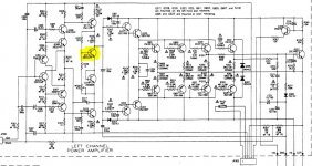
On the amp board there is a single Toshiba 2SC3423 (which is on the same heat sink as the power transistors 2SC3519/2SA1386) when I measure it - positive to Base and then negative probe to Collector and Emitter I get the expected 0.673 voltage drop, however when I switch the probes so I have negative on Base and positive on Collector and Emitter, then I get 1.8 and 1.9 voltage drop.
Shouldn't I be getting OL instead of 1.8-1.9? Does this confirm it is dead?
I'm asking because the only reasonable substitute I can find at DigiKey is a Toshiba TTC004B - not a perfect match but as close as I can find that is mountable to the heat sink.
Is this correct? Both that the 2SC3423 is bad and that the TTC004B is an acceptable substitution? I will replace it on both channels – so they have the same one, if I can’t get a more exact replacement.
I included a snippet of the schematic so you can see the position (not sure what is called in amp circuit terms - driver/pre-driver???
Attachments
You can not reliably check parts in circuit at there is far to much interaction with surrounding circuitry.
If you place a link across C319 you will force a low bias condition and barring other faults the amp would operate normally but with no bias current (so crossover distortion may be audible at low level).
That transistor is just used for thermal sensing and sees little current flow and little voltage across it. Pretty much any suitably packaged common part would work as a replacement.
I would also be very surprised if it were faulty.
Thanks Mooly - I agree it would be best to take out all the main transistor parts and test out of circuit. Worried about doing that because I have a 2-3 parts that have bad solder pads, was trying not to take something out I didn't have to.
Just thinking here - would it be better to get the "more working" channel fixed first (with you guys' help of course) so I have a working version to use for the really damaged channel?
If so - any reason why I couldn't use a +/-55vDC SMPS to power it, to take voltage tests and see if I can get it to produce sound?
Also - if it's out of circuit, meaning not in the case or connected to the protection systems (JP204/JP304) on the PSU - will it power up and work?
It appears it would, but again new to reading schematics.
I would use the original PSU with a bulb tester. Its the best option all around as the bulb limits current. An SMPS could supply enough current to be destructive and/or could be destroyed itself.
Transistors that have failed will for the most part read very low resistance (or just short circuit) in circuit, usually failing between C and E.
I would link out C319 on both channels to force minimum bias and then power up to see what happens. One of two things will occur. The bulb will not be bright and so it will allow a decent rail voltage to develop... and from there you can fault find by taking voltage measurements. Alternatively the bulb will be bright because of high current being drawn. If so we can simply locate the problem area.
Sounds good I will order the PSU parts and known bad transistors and start working on the repair. Can I leave the bad/worse channel disconnected or will it force it into protection? Hoping to work on one channel at a time.
Hi bullittstang,
The bad channel will put the unit into protect. Remove the drivers and outputs from the bad channel and hopefully everything else will survive.
In this situation I normally fix everything, then test on a variac. The reason is that you can see current draw developing at very low voltages and do more troubleshooting from there. In your case, use a very low wattage bulb, starting at maybe 25 watts, in order to get a handle on what might be wrong. Mount the bulb firmly first and then use the power switch to turn it on. Don't leave the equipment on and screw the lamps in to control when it is on or off.
-Chris
Make sense. Can you tell me what the drivers and outputs are? Assume the outputs are the TO-3’s on the heat sink and the drivers are TO-126’s on their own heat sink? Is that correct?
Correct.
You can see shorted output transistors with a DVM installed. BE or CE 1 ohm or less they are toast. (discharge mains caps before subjecting DVM to this test to protect it. Measure voltage first, discharge to <100 mv with a resistor and clip leads). Shorted drivers may show up on ohms scale too. Usually bad OT/drivers take some emitter resistors with them.
One TO126 or TO220 mounted on the output transistor heat sink would be the temperature sensor. Often taken out by the driver failures, too. Drivers would be in pairs.
One keeps checking backwards when finding blown stuff until you start finding things that weren't blown up by the raging rail voltage coming out the bass lines.
Last edited:
The outputs are on the heat sink, the drivers are normally TO-220 case style.
Okay, found the manual. The outputs are 4 transistors for each channel, 2SA1386 and 2SC3519. The drivers are 2SA1837 and 2SC4793, TO-220 case styles. It looks like it might be a really good sounding amplifier, well worth fixing. Unusual for NAD.
Also check the resistors between emitters. There are 4 0R22 resistors in the output, a 120R resistor (R349/350) and a 680R resistor (R347/348) referenced in the amplifiers, references L/R channels.
Always replace the transistors one level back past the last damaged transistor you find.
-Chris
if you like NAD sound restore the original amplifier. If not, build a better amp and use the case to house it. this is what I did with an SX-780 and SX 3700.
new amps, preamps , tuner upgrades , tube preamp & tone stack
new amps, preamps , tuner upgrades , tube preamp & tone stack
Thanks @indianajo and @anatech - I will check the transistors one more time with the ohm test you mentioned.
I also went back and checked the emitter, 120R and 680R on both amp boards and they are all within a 5% spec of the listed value. I had them as good on my schematic, so I'm pleased they checked out good the second time as well.
I finished a make-shift workbench in my basement, that way I can take the amp apart and leave it apart until it's finished (small hands seem to be drawn to screws and parts). Hope to finalize my parts order soon and then I should be able to get started next week.
Thanks again for all the replys and assistance. I will be back for more help in a week or two.
Update -
Made some progress on the PSU and took out all the caps, changed out an C2240 and correspeonding A970 transistor (Q202 & Q203) replaced two bad 1N4148's I found (actually replaced 3 but one tested good out of circuit). I tested all teh transistors 2-3 times as well as the all the resistors. I also put in a new OMRON relay since the OE seems to fail at some point.
I installed a new three-prong IEC inlet plug - the current two-prong plug had been crushed and one of the prongs was starting to come out of the plug. Not a perfect cut-out - so I'm lucky it's on the back and only seen by me.
Next step(s) it to install some quick connect plugs on the ribbon cables that attach the PSU to the amp boards and the inputs for easier disassembly (hopefully won't be needed - LOL).
A little clean-up on the chassis (small amount of rust) and I will be able to put the PSU back together and test for proper voltages. Fingers crossed it all goes well.
Then I can start roubleshooting the "good channel" and get it working, so i have a reference for the "bad channel".
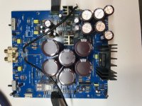
Here's a couple upgraded PSU pics for reading this. All Nichicon PS caps
Made some progress on the PSU and took out all the caps, changed out an C2240 and correspeonding A970 transistor (Q202 & Q203) replaced two bad 1N4148's I found (actually replaced 3 but one tested good out of circuit). I tested all teh transistors 2-3 times as well as the all the resistors. I also put in a new OMRON relay since the OE seems to fail at some point.
I installed a new three-prong IEC inlet plug - the current two-prong plug had been crushed and one of the prongs was starting to come out of the plug. Not a perfect cut-out - so I'm lucky it's on the back and only seen by me.
Next step(s) it to install some quick connect plugs on the ribbon cables that attach the PSU to the amp boards and the inputs for easier disassembly (hopefully won't be needed - LOL).
A little clean-up on the chassis (small amount of rust) and I will be able to put the PSU back together and test for proper voltages. Fingers crossed it all goes well.
Then I can start roubleshooting the "good channel" and get it working, so i have a reference for the "bad channel".
Here's a couple upgraded PSU pics for reading this. All Nichicon PS caps
Attachments

The emitter resistors that habitually blow with the output transistors are the 0.22 ohm ones connected to the output transistor emitters. Resistors caps and diodes associated with the driver transistors blow frequenly too. Imagine rail voltage at 500 amps raging out of the base and emitter leads of the blown output transistors. I had some 50v rated bypass caps in one of my amps that blew because rail voltage was 85. If caps don't have a suffix J or higher, they are likely low voltage B series. Capacitor testers check at 2 v so that is not a valid test for breakdown. If the associated VAS or input op amp stage didn't work right, I replaced the caps after the transistors diodes & resistors were checked. Then they started working right, except the op amp with the bad solder joint on the socket. Output went goofy latched to supply rail every time a put a meter on feedback pin.I also went back and checked the emitter, 120R and 680R on both amp boards and they are all within a 5% spec of the listed value. I had them as good on my schematic, so I'm pleased they checked out good the second time as well.
BTW, the meter ohms check (or diode check some meters) can fail blown transistors & diodes, but it can't prove them good against high voltage. I've had transistors that read okay on the DVM blow up under rail voltage. (use a light bulb current limiter in AC line to limit explosive force) I've found a leakage test at 12 v predicts blown semis pretty well. 12 v car battery charger+ capacitor or 12 to 24 v wall transfomer, 47k resistor series, put on C-E of transistors with base open, measure current. If transistor is good, current should be a lot lower than 12v/47k. Iceo spec is on transistor datasheets.
There used to be VOM that measured resistance at 22 v, but those went the way of the dodo bird. Have to build your own with the milliammeter scale of a DVM.
Last edited:
good info - I will certainly be taking the amp repair slowly too.
My wording was poor - I tested the emitter resistors (0.22 ohms) and the 120r and 680r and they are w/i 5%. I tested all the resistors on each board and ordered replacements for anything more than 10% out of spec.
I have a B&K multimeter that tests Caps and small BJT's - which I have been using as I pull parts - test and then re-install or replace. I also bought a cheap transistor tester off eBay and I run then through that too as a double check.
I will certainly test these with the DBT using a 25-watt and then 40-watt bulb. I just bought a Fluke 10, and it came with a temp sensor probe so I'm hoping that will help me check that nothing is heating up when I apply power.
Trying to be methodical while trying to understand the schematic and parts function in the circuit - slow going but learning quite a lot already.
So I have made some more progress on this project. I bought some JST disconnects for the secondary power, thermosistor and over-under current from amp-psu as well for the inputs and changed the input signal wire to Mogami mic wire.
Also I have checked all the transistors and replaced the capacitors on the right (good channel) amp board. Cleaned it up top and bottom and looks to be ready to put back in the chassis.
As for the left (bad channel) I have a few questions:
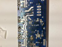
- I replaced a burnt/lifted ground track (see pic) on the bottom
- I took out all the capacitors (two of which were blown apart)
- I tested all small-signal and pre-driver transistors and found 3 bad ones - all are 2sa970's (one had the plastic case broken into pieces)
- All the power transistors (C3519, A1386) tested bad - shorted
- no other transistors failed (I pulled and tested all of them)
Is it normal for only the power transitors to fail, destroy the ground track and 3 small signal transistors, while the pre-drivers and other transistors test good?
Should I go ahead and replace the corresponding transistors? A970 is bad, replace the c2240 as well?
Also tested the PSU with a 25w, 40w and 60w DBT - and the +/- voltages test good, however it stays in Protect mode. Is this normal? Also verified the clip and bridge lights work, the switches were dirty, but cleaned and working good now.
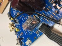
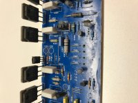
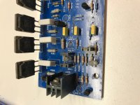
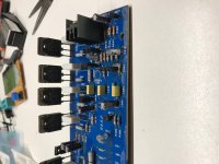
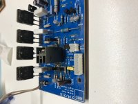
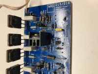
Added some pics for clarification. #1,2 are the Right channel (good) and pics #3,4,5,6 are the Left channel (bad)
Also I have checked all the transistors and replaced the capacitors on the right (good channel) amp board. Cleaned it up top and bottom and looks to be ready to put back in the chassis.
As for the left (bad channel) I have a few questions:
- I replaced a burnt/lifted ground track (see pic) on the bottom
- I took out all the capacitors (two of which were blown apart)
- I tested all small-signal and pre-driver transistors and found 3 bad ones - all are 2sa970's (one had the plastic case broken into pieces)
- All the power transistors (C3519, A1386) tested bad - shorted
- no other transistors failed (I pulled and tested all of them)
Is it normal for only the power transitors to fail, destroy the ground track and 3 small signal transistors, while the pre-drivers and other transistors test good?
Should I go ahead and replace the corresponding transistors? A970 is bad, replace the c2240 as well?
Also tested the PSU with a 25w, 40w and 60w DBT - and the +/- voltages test good, however it stays in Protect mode. Is this normal? Also verified the clip and bridge lights work, the switches were dirty, but cleaned and working good now.
Added some pics for clarification. #1,2 are the Right channel (good) and pics #3,4,5,6 are the Left channel (bad)
Attachments
Last edited:
- Status
- Not open for further replies.
- Home
- Amplifiers
- Solid State
- NAD 216 - Is it worth restoring/saving?