I'm starting to pull my hair out on this one... A little background first....
I re-purchased this amp cheap from a friend who blew it up. Most of the output transistors and their drivers on the right channel were toast.
As it sits now, there are absolutely no output transistors in it (center heat sink is completely empty) and there are no drivers in it either. I'm stumped as to why it still won't come out of protection mode. The one thing that is baffling is that I'm getting good voltages everywhere except the -45V rail (low-power side of the power envelope). I get -65.9 volts on 4-ohm switch position or -71.1 volts on 8-ohm switch position. The 10000uf/50v cap (C510) is in danger. That -71 volts travels everywhere and I don't know where it is coming from. I've checked just about every transistor, resistor, diode and cap in this thing and can't find the problem. AC voltages from the transformer to the fuses and the rectifiers are all good.
Anyone who has experience with this amp and could help me, it would be greatly appreciated.
Also, center voltage check is at -5.80 volts left channel (checked at R471) and -5.78 volts right channel (checked at R472). Obviously why it's stuck in protect.
Idle current is not adjustable (as there are no bias transistors in it) and at 5.7mV left channel and 5.4mV right channel.
Idle current is not adjustable (as there are no bias transistors in it) and at 5.7mV left channel and 5.4mV right channel.
Its might be oscillating. The circuit isn't designed to operate without those transistors, and oscillation can push back on a lightly loaded rail.
I'd suspect the rail filter caps are bad too if old, that's often a cause of oscillations.
Check the power supply ground is actually continuous with the other grounds - you need to be sure you are measuring relative to a single ground.
I'd suspect the rail filter caps are bad too if old, that's often a cause of oscillations.
Check the power supply ground is actually continuous with the other grounds - you need to be sure you are measuring relative to a single ground.
As it sits now, there are absolutely no output transistors in it (center heat sink is completely empty) and there are no drivers in it either. I'm stumped as to why it still won't come out of protection mode.
Ummm ... because it's only half there?
That amp uses the TA7317 protection chip so it's likely watching DC offsets, Thermal and/or Overcurrent situations. But it's only going to take the amp out of protection if everything it monitors is right.
Ummm ... because it's only half there?
That amp uses the TA7317 protection chip so it's likely watching DC offsets, Thermal and/or Overcurrent situations. But it's only going to take the amp out of protection if everything it monitors is right.
I had a second unit which was also under repair under the same condition (no finals or drivers) and it did come out of protection. Perhaps I should start ordering replacement parts and populate the entire board and work from there.
Here's what I'm thinking for substitutions:
Q441/442: 2SD1238 -> NTE2534 OR 2SC2837
Q437/438: 2SA1302 -> 2SA1943 OR MJW1302AG
Q433/434: 2SA1011 -> NTE398 OR MJE15033G
Q425/426: 2SC3423 -> NTE373 OR MJE340
Q435/436: 2SC2344 -> NTE375 OR MJE15032G
Q439/440: 2SC3281 -> 2SC5200 OR NTE2328 OR MJW3281AG
Q443/444: 2SB922 -> NTE2535 (NLA) OR 2SB1383
Others (drivers):
2SA1370
2SC3467
2SC1815 - common
2SB892
Wagner Online have most of those transistors.
You should also be using a 'bulb tester', do not proceed without one.
Dan.
You should also be using a 'bulb tester', do not proceed without one.
Dan.
Wagner Online have most of those transistors.
You should also be using a 'bulb tester', do not proceed without one.
Dan.
Will check that out. And yes, DBT is always on the bench.
Here's what I'm thinking for substitutions:
Q441/442: 2SD1238 -> NTE2534 OR 2SC2837
Q437/438: 2SA1302 -> 2SA1943 OR MJW1302AG
Q433/434: 2SA1011 -> NTE398 OR MJE15033G
Q425/426: 2SC3423 -> NTE373 OR MJE340
Q435/436: 2SC2344 -> NTE375 OR MJE15032G
Q439/440: 2SC3281 -> 2SC5200 OR NTE2328 OR MJW3281AG
Q443/444: 2SB922 -> NTE2535 (NLA) OR 2SB1383
Some people frown on NTE, they claim to be a match but on closer inspection... so they are relegated to absolute last resort. No issue with MJE's...
From experience Wagner transistors are all originals, the only one not listed is 2SD1238.Will check that out. And yes, DBT is always on the bench.
You can and should run this amp with drivers normally connected and OP transistors with Collector pin disconnected.
This completes the NFB loop and with no load connected the amp should DC balance and be able to drive headphones ok, but NOT speakers.
If still faulty you can work your way back through the circuit, and I advise running a lower wattage bulb (25W/40W) during this fault finding, once all is mostly proven good swap up to 100W+ bulb and preset bias current and allow to stabilise before powering directly and final bias current cal.
Also, center voltage check is at -5.80 volts left channel (checked at R471) and -5.78 volts right channel (checked at R472). Obviously why it's stuck in protect.
Idle current is not adjustable (as there are no bias transistors in it) and at 5.7mV left channel and 5.4mV right channel.
If the center voltage is off I would suspect a blown off zero volt line track/wire.
I had a similar problem with a stripboard amp I built.
The output shorting blew out the zero volt track on the strip board and left all sorts of weird voltages.
on the rail voltages...
would you happen to be in a 220/240 area and have it wired for 100/120?
No, in 110 area and it is a 110 unit.
If the center voltage is off I would suspect a blown off zero volt line track/wire.
I had a similar problem with a stripboard amp I built.
The output shorting blew out the zero volt track on the strip board and left all sorts of weird voltages.
I have checked every trace under the microscope and also done point-to-point continuity testing. I did find a broken trace, but that has been repaired. -45 rail is still at -71V.
what does the rail to rail measure -45 to +45 .... if grand to r4ail is 71 v is the rail to rail 142v?
what does the rail to rail measure -45 to +45 .... if grand to r4ail is 71 v is the rail to rail 142v?
A little over 125V.
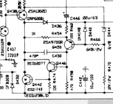
You mention outputs and drivers but have you checked the rail switching transistors and their commutation diodes? Any of the semiconductors here could have failed allowing the high voltage to couple into the low voltage rail.
That pic is a little foggy. Which specific transistors and diodes?
are you sure the filter cap is functional, almost sounds like you might be reading the peak voltage the rectified output. do you have the ability to put a scope on the dc rail? if not maybe you could just use the ac function of your meter and see if you are reading any significant ac voltage.
Last edited:
Filter caps were taken out and measured. All seemed within spec. Upon further measurements, there is identical voltage between the negative high voltage rail cap (C508) and negative low voltage rail (C510). Both are at -74.8V. There must be a short somewhere between the two as suggested by Mooly.
- Home
- Amplifiers
- Solid State
- NAD 2100 in protection, -45V rail too high