Hi there,
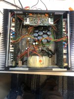
I have bought an NAD 208 a while ago and was quite happy with it. Missed the last bit of transparency and spaciousness and got inspired by the mod replacing the 2 stock NE5532s with LM4562s. So unsoldered the NE5532s and put DIP IC sockets in. Just to be on the safe side I placed new NE5532s (triple check orientation) in there.

Switching it back on the unit stayed in protection mode for 5 seconds, switched to green for another and back to protection mode, and so on: YouTube
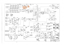
I reviewed the service manual and to be honest, the protection circuit description is too much for me to comprehend (quite an newbie in electronics). Seems it measures several different things, so difficult to predict where the problem comes from.
So, I am looking for help to reduce the potential source of problems:
- Is the protection mode at all influenced by the input amplifier board or can I stop worrying that I messed something up on the input board . I double-checked the soldering points and they look really good (my soldering skills are quite ok). But if I know that the cannot be the problem, I can follow the typical "protection mode" related solution paths.
- Is it possible/likely that I fried some neighbouring components on the input board which now cause the problem?
- Might the unit just require adjustment of idle current or CMMR (Common Mode Rejection Ratio)?
Appreciate any guidance on this. I want my amp back!
Thanks,
Christian
I have bought an NAD 208 a while ago and was quite happy with it. Missed the last bit of transparency and spaciousness and got inspired by the mod replacing the 2 stock NE5532s with LM4562s. So unsoldered the NE5532s and put DIP IC sockets in. Just to be on the safe side I placed new NE5532s (triple check orientation) in there.
Switching it back on the unit stayed in protection mode for 5 seconds, switched to green for another and back to protection mode, and so on: YouTube
I reviewed the service manual and to be honest, the protection circuit description is too much for me to comprehend (quite an newbie in electronics). Seems it measures several different things, so difficult to predict where the problem comes from.
So, I am looking for help to reduce the potential source of problems:
- Is the protection mode at all influenced by the input amplifier board or can I stop worrying that I messed something up on the input board . I double-checked the soldering points and they look really good (my soldering skills are quite ok). But if I know that the cannot be the problem, I can follow the typical "protection mode" related solution paths.
- Is it possible/likely that I fried some neighbouring components on the input board which now cause the problem?
- Might the unit just require adjustment of idle current or CMMR (Common Mode Rejection Ratio)?
Appreciate any guidance on this. I want my amp back!
Thanks,
Christian
Last edited:
You are too new for your pictures to load up. Or you are failing to "go advanced" (button on the bottom of post) and load up an image from your hard drive or a web source.
Check your power supplies at the op amps. + and - 15 or any other + - voltage on pins 8 & 4. I use a cut off stiff lead for this in a pamona grabber, so there is little chance of shorting power supply to output pin and blowing up the IC. Use reading glasses & a lot of light. From the top pin 1 is the one with the dot, or the one on the left of the end that has the dimple in it. You count counter-clockwise from the top. Top is the side with lettering on it.
Notice to newbies, voltage over 24 across your heart can stop it. Use one hand at a time, especially with the power on. For the meter negative probe, use an alligator clip lead to speaker ground. Which you put on with one hand. 30 A Current from a 1 v source can burn your flesh to charcoal. No jewelry on fingers, hands, or neck. Check metal is below 1 v to ground before touching it with hands. Don't work alone and don't work distracted by conversation, media, anything else.
Not checking google drive, I've gotten virus from poorly supervised websites. Plus google gives away a poor resolution picture, requiring users to sign in to see a good one. I don't have a google identity, will not ask for one. They already track me every second that I'm within an electrical network. Fortunately my cell phone is anonymous, the kind favored by homeless people.
If power supply is gone, likely you shorted it to something else while soldering. If the protection IC is a TA7317, yeah, they have several inputs, and are obsolete as buggy whips. Don't blow it up.
BTW 4562 has a lot faster slew rate than 5532, and will require 0.1 uf ceramic caps between power supplies within 1" of each IC. Also needs 33 pf disk cap around the feedback resistor. This reduces tendency to oscillate. Peavey uses NJM4560 for this kind of service, doesn't require all the accessories. But 5532 is not bad for audio, not noisy, bit of a power supply hog but NAD put enough oomph in the power supply for that.
Second check is for DC going into the protection relay. Over 0.2 v, you have a problem in the amp section. Usually there is a big coil, 1 cm x 5 cm, right before the protection relay input. Follow the trace.
Last edited:
My suggestion :
Unplug the mulit-cable connect in the middle of the input board (isolate the input board power, the final power amplifier section is independent from the input board, they couple by capacitors), turn on power to check the speaker protection ok or not. If it function ok then the input board must something go wrong. Recheck your last mod soldering or op-amp IC is OK or not.
Unplug the mulit-cable connect in the middle of the input board (isolate the input board power, the final power amplifier section is independent from the input board, they couple by capacitors), turn on power to check the speaker protection ok or not. If it function ok then the input board must something go wrong. Recheck your last mod soldering or op-amp IC is OK or not.
First of all, thanks for your recommendations, indianajo and patrick! I'll follow your suggestions and report back on progress.
Difficult to do as the multi-cable is soldered to the input board and not a connector in my case. Will try to do from the other (power board) side.
Unplug the mulit-cable connect in the middle of the input board (isolate the input board power, the final power amplifier section is independent from the input board, they couple by capacitors), turn on power to check the speaker protection ok or not.
Difficult to do as the multi-cable is soldered to the input board and not a connector in my case. Will try to do from the other (power board) side.
Last edited:
Those are turned-pin IC sockets, most ICs are standard flat pins, which need a standard IC socket with flat spring contacts.
Those are turned-pin IC sockets, most ICs are standard flat pins, which need a standard IC socket with flat spring contacts.
Well spotted, Mark. I replaced this already with standard flat spring IC sockets and triple checked the solder points for them (basically the only soldering that I previously did on the board). No improvement.
patrick101 said:(isolate the input board power, the final power amplifier section is independent from the input board, they couple by capacitors), turn on power to check the speaker protection ok or not
Did that, the only change was that the amp stayed in protection mode (red) without even clicking and changing to green for a sec (before switching back to red).
Opamps are ok, checked them on a preamp. I might have initiated a cold solder point by playing with the input board and fiddling around in the amps belly 🙁 Does not make it easier to find the problem ...
Those are turned-pin IC sockets, most ICs are standard flat pins, which need a standard IC socket with flat spring contacts.
Umm what? Turned pin sockets are made for all ICs. Flat sockets are much worse, as they only make contact on two sides of the pin.
The only advantage of dual wipe sockets is they’re cheap.
If you do have DC coming out of the junction of the pnp/npn output transistor emitter resistors, then one backs up with the DVM and looks at the first stage the DC unbalance was coming from. One of my amps, the 2nd op amp the feedback pin was not connecting the board sometimes. op amps all 3 pins, 2 in, 1 out, should be the same voltage when input shorted. The first stage where the DC is, there you should probe around looking for trouble. Capacitor or diode with same DC voltage on both sides, transistor without +-0.6 v DC base to emitter, input or VAS transistor without collector between 1/3 to 2/3 of rail, resistor with more voltage across it than the wattage allows (burnt out). Lots of symptoms tell you what the problems is just with a DVM.check is for DC going into the protection relay. Over 0.2 v, you have a problem in the amp section. Usually there is a big coil, 1 cm x 5 cm, right before the protection relay input. Follow the trace.
Normal NAD 208 turn on no red light and with a few minutes later just green light on.
Your amp turn on red light when you power up and the red light on means the heatsink temperature sensor open circuit. Please check the cable connection problem or just the sensor open circuit(sensor should be close contact in normal).
Your amp turn on red light when you power up and the red light on means the heatsink temperature sensor open circuit. Please check the cable connection problem or just the sensor open circuit(sensor should be close contact in normal).
Attachments

Gentlemen,
thanks for your encouraging tips so far. I have not been able to work on this issue as Corona also hit Austria and I had to deal with other problems.
I as just about to order some parts to replace the caps and IC on the protection circuit and decided to check on the fuses once more. I was sure I checked them but I was proven wrong. The 10A (F502) fuse was blown. Replaced it with a fresh one this morning and it immediately blew when switching on the amp.
So, the whole protection mode problem might have it's cause somewhere else, misleading us to look at the wrong place.... sorry for that.
Nevertheless, I would still like to get it up and running, so here is my plan:
- Exchange BR501 and C518

Question is whether this will solve anything or a blowing fuse like this might have a lot of different causes? Would you recommend replacing other parts and give it a try?
Gentlemen,
thanks for all your recommendations and apologies for the late reply. Covid-19 also hit Austria and I had other issues to deal with.
I was just about to order some spare parts for the 208 to replace the caps and IC of the protection circuit when I retested the fuses. I was sure I tested them, but was proven to be wrong. The 10A fuse (F502) was blown and after replacing it with a new one, it blew up in the second I switched on the amp. So there might be a completely different cause for the protection circuit problem we were discussing before.
So, my plan is to replace the bridge rectifier BR501 and cap C518 (10nF, 250V) as the are following in the path.
Does this make sense or might the problem come from the other side. Or might the blowing fuses be caused by some deeper problem burried in the labyrinth of the schematic?
Thanks again for your recommendations!
Attachments
 Merged two posts
 The 10A fuse (F502) was blown and after replacing it with a new one, it blew up in the second I switched on the amp. So there might be a completely different cause for the protection circuit problem we were discussing before.
So, my plan is to replace the bridge rectifier BR501 and cap C518 (10nF, 250V) as the are following in the path.
Does this make sense or might the problem come from the other side. Or might the blowing fuses be caused by some deeper problem burried in the labyrinth of the schematic?
First you can take out the the bridge rectifier BR501 and cap to test if they are failed, after that you should measure the bridge rectifier output sides +v and -V if there are any short circuit, if no short circuit in both output sides, you can try put back good bridge rectifier BR501, cap and fuse to test.
Good luck!
Christian did you get a result. On your NAD208 protection problemHi there,
I have bought an NAD 208 a while ago and was quite happy with it. Missed the last bit of transparency and spaciousness and got inspired by the mod replacing the 2 stock NE5532s with LM4562s. So unsoldered the NE5532s and put DIP IC sockets in. Just to be on the safe side I placed new NE5532s (triple check orientation) in there.
Switching it back on the unit stayed in protection mode for 5 seconds, switched to green for another and back to protection mode, and so on: YouTube
I reviewed the service manual and to be honest, the protection circuit description is too much for me to comprehend (quite an newbie in electronics). Seems it measures several different things, so difficult to predict where the problem comes from.
So, I am looking for help to reduce the potential source of problems:
- Is the protection mode at all influenced by the input amplifier board or can I stop worrying that I messed something up on the input board . I double-checked the soldering points and they look really good (my soldering skills are quite ok). But if I know that the cannot be the problem, I can follow the typical "protection mode" related solution paths.
- Is it possible/likely that I fried some neighbouring components on the input board which now cause the problem?
- Might the unit just require adjustment of idle current or CMMR (Common Mode Rejection Ratio)?
Appreciate any guidance on this. I want my amp back!
Thanks,
Christian
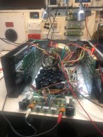
I have just fixed a NAD208 happy to help you with working it out as I eat and breathed this model for 6 months rebuilt after both outputs destroyed
Cheers
Wayne
Attachments
- Home
- Amplifiers
- Solid State
- NAD 208 protection mode