crissty said:everything seems to be OK,
i got the schematic from www.oliveaudio.com
I also wonder why Lars have removed it from his LCaudio website and its nowhere to be found, also the was a copy of schematics at by dx.master as below:
--------------------------------------------------------------------
Please look on my site:
- http://bauteile-fuer-die-elektronik.de/projekte/ZETA/
Spezial at
- http://bauteile-fuer-die-elektronik...lcaudiozeta.gif
regards,
dx.master
-----------------------------------------------------------------------
this is also removed.
If its been designed for DIY, why in the hell all schematics have been deleted.
WONDERING WHY................
Sorry my Website has a new place:
http://bauteile-fuer-die-elektronik.akadns.de/projekte/ZETA/
Interesting, the ZETA project is going underground 😉
Now how about spreading some up to date information? Some people on this forum really invested some time and effort into this project and are now waiting, at least for a final statement.
Sebastian.
Now how about spreading some up to date information? Some people on this forum really invested some time and effort into this project and are now waiting, at least for a final statement.
Sebastian.
Hi Lars,
nice to hear from you again. 😉
I had checked oliveaudio.dk from time to time before. I was just wondering wether You're still spending some time on the ZETA.
I understand that you don't want to give away a good amplifier design for free to everyone who asks, as a full DIY project description would of course be more than a schematic!!!
So I guess - as a good engineer - you're expecting a little more practical work from your students...

Cheers,
Sebastian.
nice to hear from you again. 😉
I had checked oliveaudio.dk from time to time before. I was just wondering wether You're still spending some time on the ZETA.
I understand that you don't want to give away a good amplifier design for free to everyone who asks, as a full DIY project description would of course be more than a schematic!!!
So I guess - as a good engineer - you're expecting a little more practical work from your students...


Cheers,
Sebastian.
sek: if you look on www.oliveaudio.com you can see already the new schematics and PCB
Lars, I thank you in the name of all DIY-ers of ZETA.
Guys, check on www.oliveaudio.com for the PDF file for mini-ZETA.
Lars, I thank you in the name of all DIY-ers of ZETA.
Guys, check on www.oliveaudio.com for the PDF file for mini-ZETA.
Hi again, Lars,
a respectful THANK YOU!
I'm staying tuned. 😉
Hi Bubu,
thank you, too!
Sebastian.
a respectful THANK YOU!
I'm staying tuned. 😉
Hi Bubu,
thank you, too!
Sebastian.
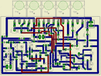
Preliminary Zeta PCB
Howdy people. Here's a preliminary ZETA PCB with 5 output devices. Preliminary because I intend to make it single layer... If anyone interested to build it as is, I'll post the PDF. Dimensions are 11,5 cm / 7 cm. Sorry but these are Eagle's limitations... I know it looks a little bit messy but what to expect from something done in few hours? I'll try to improve it. Next week-end.
Valentin
Attachments
Hi Bubu,
some of your tracks are a little close to each other.
Try adding alternative cap pitch options.
Are your resistors mounted end on?
Why an odd number of output devices, I would expect to see even numbers (pairs)?
some of your tracks are a little close to each other.
Try adding alternative cap pitch options.
Are your resistors mounted end on?
Why an odd number of output devices, I would expect to see even numbers (pairs)?
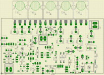
Ok Andrew you're right. I'll change some footprints and try a new pcb 13/10 cm this time, with a lot of space between tracks (Using the same topology from eagle I will try it in ExpressPCB).AndrewT said:Hi Bubu,
some of your tracks are a little close to each other.
Try adding alternative cap pitch options.
Are your resistors mounted end on?
Why an odd number of output devices, I would expect to see even numbers (pairs)?
). What do you mean with alternative cap pitch options? All components are on top layer very close to each other... About the odd number of output devices you forgot the IRFP9240 driver. I will build this amp and make all my speakers active.
Cheers!
Valentin
Attachments
Hi
I'm going to build a ZETA powered car-amp, and I'm building it all SMD, for a small size, and of course, because I like SMD... 🙂
I'm having trouble finding SMD replacements for transistors, and since this project is a rather low power, I was wondering about the specs of these. I'm using 30V rails, aiming for 80W@4ohms or something like that. Is it OK to replace the 150 Volt 2N5550/2N5401 with more common 65 volts transistors in this low power unit? maybe BCP846/BCP856 ( 0.1W 0.25A 65V approx 300-400 hFE )
The same for the MPSA42/92:s, maybe replacing them with the BCP53/56 ( 1,5W 80V 1A )
For up to 100W in 4 Ohms you need a rail of only 32 V DC, so you can safely use BC846 / BC856 to replace both 2N's and MPSA's.
Not BCP's 😀
Not BCP's 😀
What happened to the high power version?
Ok I really liked the idea of the 1000W overpowered version, what happened Mr. Clausen? I am an avid enthusiast and I was about to start working on my own build, but now I see no plans?
What is the plans for the high powered version, and can I find it anywhere?
Ok I really liked the idea of the 1000W overpowered version, what happened Mr. Clausen? I am an avid enthusiast and I was about to start working on my own build, but now I see no plans?
What is the plans for the high powered version, and can I find it anywhere?
Hi Lars,
So you have been working on Zeta version 2 ,
You have written that there is 50% crossconduction above 1khz that means no cross conduction in subwoofer use , next can I have the data of the extra NPN Tr you have added at the gate of the -ve side output mosfet ( please also explain its advantage )
Rajeev
Rejeev: The NPN transistor is working like a simple VBE multiplier, and creates an offset of the gate voltage, allowing for a smaller rail loss on the - rail.
Any small signal darligton can be used.
Best regards
Lars C
Any small signal darligton can be used.
Best regards
Lars C
- Home
- Amplifiers
- Solid State
- N-Channel mosfet amplifier schematic needed

