I know, but according to PMA, amplifiers tend to be inductive even with flat loop gain and no output inductor. The only reasons I can think of are wiring or some local loop losing loop gain, but maybe there is something else going on.
DF is not that big a deal for HF drivers as it is for woofers since moving mass is so much smaller for the HF drivers. So if DF decreases at high frequencies, it is not likely to be consequential, sound-wise. Even for woofers very large DF is not that important, since the DCR of the woofer's voice coil will minimize the damping effect of such a low source impedance. So DF is important, but large amounts of it are unnecessary. Since with modern S.S. amplifiers, high DF comes with, then there's not even any point in worrying about having enough.Not entirely so, the output impedance may have and usually has pronounced inductive component (even without output coil) and you do not see it in the loopgain plot. Method of injected current into amp output reveals this. DF then decreases at high frequencies.
Last edited:
Probably, output wiring is enough for that effect. It is visible only at very low output impedances, where some 150 nH of internal wiring is enough to show above 10 kHz.Not entirely so, the output impedance may have and usually has pronounced inductive component (even without output coil) and you do not see it in the loopgain plot. Method of injected current into amp output reveals this. DF then decreases at high frequencies.
There is an interesting question as why that inductive component is not visible if measuring output impedance by loading amplifier output. Here is my example measurement using both methods.
In my country, there is a saying which translates as “What are you baffled with as is a turkey with turd?”. Whoever saw live that big bird cocking its head examining turd to determine is it something to eat would understand. It’s hilarious.
So, I was as a proverbial turkey wondering why results from two methods doesn’t match. Eventually, Elvee offered an explanation which I was able to replicate with LTSpice, to match both measurement method results.
https://www.diyaudio.com/community/...-measurement-without-load.403745/post-7505816
MarcelvdG, jan.didden - The loop gain can be flat only up to some frequency. Above that, the loop gain must fall and the output will appear inductive.
Ed
Ed
Pls keep in mind that even the simple emitter follower has an inductive output impedance due to the decreasing current gain vs frequency. This explains instability with capacitive load.
That's an example of dropping local loop gain, but isn't fT/hfe above the audio band? Well, maybe not with epitaxial-base transistors biased at a small quiescent current.
Even a global feedback loop's -3dB point can be above the audio band (i.e. "Low TIM" amplifiers).
Ed
Ed
I think this varies. And even in case this corner frequency is above the audio band - it may oscillate at higher frequencies.That's an example of dropping local loop gain, but isn't fT/hfe above the audio band?
@EdGr Indeed, but we are trying to reverse-engineer this comment from @PMA :
PMA: "Not entirely so, the output impedance may have and usually has pronounced inductive component (even without output coil) and you do not see it in the loopgain plot. Method of injected current into amp output reveals this. DF then decreases at high frequencies."
So, how do you get inductive behaviour at frequencies where the (overall) loop gain is flat? One possibility is the wiring inductance @tombo56 wrote about, if the output resistance is small enough. 100 nH and 5 mohm gives a corner frequency at about 8 kHz, for example. Another could be some local loop, like the emitter followers @bucks bunny mentioned, but then fT/hfe has to roll off at audio frequencies - which it maybe does when you have really slow power transistors at low currents.
Jan , my reasoning is that if by one(constant output voltage type) power amp loop gain (or feedback factor) is linear and equal over entire audio spectrum than must be the same with Damping Factor .
PMA: "Not entirely so, the output impedance may have and usually has pronounced inductive component (even without output coil) and you do not see it in the loopgain plot. Method of injected current into amp output reveals this. DF then decreases at high frequencies."
So, how do you get inductive behaviour at frequencies where the (overall) loop gain is flat? One possibility is the wiring inductance @tombo56 wrote about, if the output resistance is small enough. 100 nH and 5 mohm gives a corner frequency at about 8 kHz, for example. Another could be some local loop, like the emitter followers @bucks bunny mentioned, but then fT/hfe has to roll off at audio frequencies - which it maybe does when you have really slow power transistors at low currents.
There doesn’t appear to be any evidence that pathologically low damping factors have a beneficial effect on sound quality. You read about ‘iron fisted control over the speakers’ in reviews by journalists who’ve been told it’s important. It’s nonsense.
Yessir, for decades the ohmic resistance of the voice coil was the elephant in the room. But then came the marketing league...
That's only partly true. Loudspeakers are usually designed to have some desired response when driven from a voltage source, the effect of voicecoil resistance is taken into account during the design (and crossover component resistance can also be taken into account). It makes sense to keep the output impedance of the amplifier small compared to the voice coil resistance, because it is not taken into account by the loudspeaker system designer - but whether it is 1 % or 0.001 % of the voice coil resistance makes no practical difference at all, especially not after you look up the temperature coefficient of the resistance of copper.
(This is all assuming that the small-signal response is what matters. To keep the non-linear distortion of the loudspeaker low, a voltage source may actually be the worst choice possible.)
(This is all assuming that the small-signal response is what matters. To keep the non-linear distortion of the loudspeaker low, a voltage source may actually be the worst choice possible.)
The Arpeggio speaker designed by Morgan Jones wants a 3 ohms amp output resistance for best performance.
It was specifically developed to be mated with things like SE tube output amps.
But that is more the exception than the norm, most speakers are designed with a very low drive impedance in mind as Marcel mentions.
Jan
It was specifically developed to be mated with things like SE tube output amps.
But that is more the exception than the norm, most speakers are designed with a very low drive impedance in mind as Marcel mentions.
Jan
I know, but according to PMA, amplifiers tend to be inductive even with flat loop gain and no output inductor. The only reasons I can think of are wiring or some local loop losing loop gain, but maybe there is something else going on.
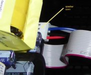
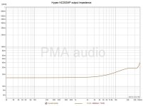
I expect we are talking about real amplifiers, not about their simplified versions in simulators. Real world parasitic impedances may not be omitted. In case of class AB amplifiers with very high feedback factor, or SOTA class D designs like NCore or Purify, all with "pure" output impedance in milliohms in low and mid frequency band, both PCB speaker connector and output binding post contact resistance (order of milliohms) and wire (from PCB to binding post) inductance (order of 0.1uH) must be taken into account. In some cases, they would dominate in output impedance. I am not speaking about speaker cable now, but amplifier output binding post is a limiting point where to measure output impedance that makes some practical sense. IMO the pure textbook theory is only good if it stays in some correspondence with reality.
Example of NC252MP


Marcel, a damping factor of 100-200 is fine (and relatively easy to achieve I believe) and once cabling is included is pretty much the norm. Damping factors of 1000 (eg claimed by some Accuphase amplifiers) are surely wasted - that’s all I’m saying. I think we have to consider all the factors between the amplifier feedback tap-off point and the speaker voice coil. I’d be surprised if these in total were less than 100 mOhms and ultimately set an upper limit on damping in a conventional setup.That's only partly true. Loudspeakers are usually designed to have some desired response when driven from a voltage source, the effect of voicecoil resistance is taken into account during the design (and crossover component resistance can also be taken into account). It makes sense to keep the output impedance of the amplifier small compared to the voice coil resistance, because it is not taken into account by the loudspeaker system designer - but whether it is 1 % or 0.001 % of the voice coil resistance makes no practical difference at all, especially not after you look up the temperature coefficient of the resistance of copper.
(This is all assuming that the small-signal response is what matters. To keep the non-linear distortion of the loudspeaker low, a voltage source may actually be the worst choice possible.)
🙂
DF > 1000 is nothing but another marketing trick. Those techno-marketing tricks are not any better than voodoo-marketing tricks. Both serve the same purpose. There are technical reasons why measurements of output impedance do not equal and do not confirm those marketing numbers, see my previous post. “White papers” issued by manufacturers often do a dirty, black job.
DF > 1000 is nothing but another marketing trick.
It is only if stated that it brings any improvement in audio reproduction over DF in the 100 – 200 range. Otherwise it is a mere fact or objective measure of amplifier properties. I have DF of 1300 in the LF range, not because that was sought but because it is an inevitable consequence of high NFB, required for low distortion.
High DF can be easily “cured” with resistor. Opposite is not possible.
When claiming this, please kindly show me a measurement on a REAL amplifier made at its output binding posts. No simulations, please. Simulations not even take PCB tracks parasitic impedances into account, not speaking about connectors contact resistance and output wire R + jwL. Real world results, please. In simulations, we all have milliohm Zout. Show it in measurements, please.I have DF of 1300 in the LF range,
- Home
- Design & Build
- Electronic Design
- Myths, tricks and hey, that's neat!