Rayma,
That's why I've always looked for a tutorial with graphics illustrating feedback types around a single triode.
At any rate thanks for the explanation for notation. I'll start on the paper you linked . There may be more questions . : ). Thanks again.
That's why I've always looked for a tutorial with graphics illustrating feedback types around a single triode.
At any rate thanks for the explanation for notation. I'll start on the paper you linked . There may be more questions . : ). Thanks again.
There were rather extensive mathematical treatments of some tube circuit examples starting on page 317,
in the 4th edition of Radiotron. Of course, everyone uses different notation.
in the 4th edition of Radiotron. Of course, everyone uses different notation.
This is a different issue than feedback per se. If you grok feedback, the concept, that's fine.While it's easy enough to see where feedback is being applied , I would still like to see explanations that make sense of the series or shunt derived, series or shunt applied designations , starting with tube circuits. Anybody got one?
Then you realise that it involves a way of, say 'combining' a sample of the output with the input signal, the result of which then forms the effective amplifier input signal.
The various series, shunt, etc are just means of how to combine the output sample with the input; just some circuit tricks, having nothing to do with the feedback concept. Those 'tricks' are the same whether you use tubes of FETs or opamps. If there's a resistor from signal input to the amp input terminal, and another (feedback) resistor from (part of) the output to the same amp input pin, then looking from the output you see those two resistors in series which we then call series feedback.
If the input signal goes to the noninverting input of the amp, and the feedback resistor goes to the inverting amp input, then the two signals look as it they are in parallel and it is shunt feedback. Easy peasy ;-)
Derived is similar. If you pick off the feedback signal from the top of your speaker as usually is done. you take off the signal in parallel or as a shunt from the output - shunt derived. If you put a small sense resistor in series with the speaker and you pick off the feedback signal from that sense resistor, the signal pickoff is in series with the output current in the speaker - series derived.
To make it worse, in this case the feedback signal depends on the current through the speaker (which flows through the sense resistor) so this is also called current feedback in the traditional sense.
Easy peasy ;-)
Combine it all and you get your usual alphabet soup.
Jan
Last edited:
I've mentioned this idea in other threads, but one way I sometimes look at feedback is in the frequency domain. I just find it easier that way, as I can do certain things that "aren't allowed" conventionally, like refining a signal multiple times in a loop. Since I'm manipulating frequencies, not samples, it all happens in parallel, at the same time.
So, for instance, I input a sine wave into a slightly non-linear amplifier, and take the output as a sine wave with a bit of 2nd harmonic. That gets attenuated X:1 by the gain-setting resistors, and sent back to the inverting input.
The amplifier sums the + input and the - input, so the fundamental waves mostly cancel out. The interesting part is when the combined input is no longer a pure sine, but a combination of input and residual error frequencies.
The 2nd harmonic and the input pass through the amplifier together (in this simplified analysis zero time has passed, so it is OK to go back). But notice what happens: intermodulation side bands as the 2 frequencies offset each other while getting distorted. Since the frequencies are harmonically related, the sidebands are also harmonically related, so one of them may be called 'H3', and another one could be 0Hz or a DC offset.
This can be done repeatedly, until the system breaks: such high frequencies are reached that it becomes unrealistic and doesn't take into account things like phase shift.
It's a simplification to allow quick understanding. If you really go into complex feedback control systems like missile guidance systems, you really have to take account of the reverse transmission from amp input through the feedback network directly to the load. This is never an issue in audio, but it can be an issue elsewhere.The arrow is part of the label for the transfer function A->
Its implicit meaning is that signal flow through the gain block A-> is unilateral,
that there is no reverse transmission through it.
Jan
Here are the canonical feedback forms:-

I also find all this ‘shunt-series’, series-series’ stuff quite confusing and completely unnecessary. In the context of amplifier electronics it’s much easier to think of it like this:-
Voltage output with voltage feedback (classic VFA)
Voltage output with current feedback (classic CFA)
Current output with voltage feedback
Current output with current feedback
Indeed, for very complex feedback systems as in aerodynamics or missile guidance, you will need the formal control definitions for the reasons Jan states but for the simple stuff we do in audio, probably not.
YMMV.

Well unless:It's not rocket science!
🤣 🤣for very complex feedback systems as in aerodynamics or missile guidance, you will need the formal control definitions
In Tritschler's article he calls the second stage feedback network shunt-shunt , yet both input and feedback go to the inverting input.If the input signal goes to the noninverting input of the amp, and the feedback resistor goes to the inverting amp input, then the two signals look as it they are in parallel and it is shunt feedback.
Also:
Referencing the image Bonsai posted , If I see the triangular amp symbol as a triode , then the + pin would be cathode, - pin would be grid , and output would be (in most cases) equivalent to the plate. Yes?
Attachments
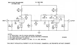
I think Bonsai's overview nailed it. But if you have another opinion, surely you can find someone on the net that supports you! ;-)In Tritschler's article he calls the second stage feedback network shunt-shunt , yet both input and feedback go to the inverting input.
In grounded cathode, the cathode is the reference for both input and output and is in phase with the input.Referencing the image Bonsai posted , If I see the triangular amp symbol as a triode , then the + pin would be cathode, - pin would be grid , and output would be (in most cases) equivalent to the plate. Yes?
Jan
I think Bonsai's overview nailed it. But if you have another opinion, surely you can find someone on the net that supports you! ;-)
No need for the sarcasm Jan. I know it's your pet peeve but you might have taken the trouble to notice that I don't know enough about this subject to have an opinion.
The only thing I'm looking for is understanding that allows me enough clarity to judge for myself. When EE's appear to contradict each other it becomes important.
Thanks
Maybe I should add the simple definitions I put up to the canonical feedback forms on my slide above.Nice overview Andrew. I think I might have it reversed in my earlier post.
Nevertheless, there is a logical system to it and when you really want to understand it, you will.
It's not rocket science!
Jan
The only thing I'm looking for is understanding that allows me enough clarity to judge for myself.
This is pretty clear. Where you see shunt, read parallel instead.
https://www.tutorialspoint.com/amplifiers/amplifiers_feedback.htm.
Here are the canonical feedback forms:-
View attachment 1332125
I also find all this ‘shunt-series’, series-series’ stuff quite confusing and completely unnecessary. In the context of amplifier electronics it’s much easier to think of it like this:-
Voltage output with voltage feedback (classic VFA)
Voltage output with current feedback (classic CFA)
Current output with voltage feedback
Current output with current feedback
Indeed, for very complex feedback systems as in aerodynamics or missile guidance, you will need the formal control definitions for the reasons Jan states but for the simple stuff we do in audio, probably not.
YMMV.
Current feedback used to mean series feedback at the output. It's a pity some idiot abused the term decades ago and that got more usual than the original definition.
Also:
Referencing the image Bonsai posted , If I see the triangular amp symbol as a triode , then the + pin would be cathode, - pin would be grid , and output would be (in most cases) equivalent to the plate. Yes?
There is something wrong with the triangle symbol: the current that flows through the output has nowhere to go. Both input currents are zero for an ideal op-amp and small for a real op-amp, so the current through the output has no return path, it just vanishes into thin air.
When you add a return pin (*) for the output current, you have one pin more than a triode, so you see that you cannot directly translate the triangle pins to triode pins.
Jan explained the problem with the triode: the cathode is a shared input and output pin. The triode is driven by the voltage between grid and cathode and responds with a current from anode to cathode. You can therefore only use a single triode for feedback configurations that have a short between an input and an output terminal.
(*): Conceptually one return pin would suffice, even though in an ordinary op-amp, the return current is actually split in a non-linear fashion between two supply pins.
Last edited:
I wrote this in answer to Rayma well before you posted Marcel but the connection dropped and had to wait. Perhaps it's more of the same sort of problem. Nevertheless, I'll post it because I'm fairly confident there are others who understand it as little as I do.
Maybe this is a good time to ask about one of the things that I can't seem to get right .
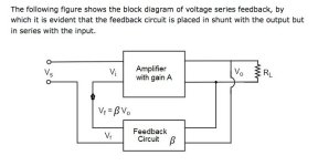
Attached from the above linked tutorial page is the often used Voltage-Series graphic along with its explanation stating that the the series connection with the input is evident. To me it's not.
What I see is the source common routed into the feedback network and apparently in series with that at the other end of the feedback network the connection goes to amplifier output positive. Ok, that looks like it could be negative feedback , or rather positive feedback to the source negative.
Then there is the other loop taken from the amplifier output negative to the amplifier input negative, thus being a loop that is not connected to the source .
In other words, what I see in this diagram is no shared common between input and output. The two rectangular blocks being black boxes.
OF COURSE I know (or assume) that interpretation is not what was intended. What I'm looking for is an explanation that follows beginner's rules (ie. if it's in series , show it like it is etc) and while I do appreciate Bonsai's friendly statement that the hyphenated terms aren't really necessary for this level of audio, the problem is that not knowing what they mean makes it impossible to learn from what others have written - being that almost all tutorials and papers use these terms, though apparently often incorrectly or at least in contradiction to what a what another one does.
(And my contention from the start is that there are more than likely others who have the same sort of trouble with as I do. It's not rocket science. : )
Maybe this is a good time to ask about one of the things that I can't seem to get right .
Attached from the above linked tutorial page is the often used Voltage-Series graphic along with its explanation stating that the the series connection with the input is evident. To me it's not.
What I see is the source common routed into the feedback network and apparently in series with that at the other end of the feedback network the connection goes to amplifier output positive. Ok, that looks like it could be negative feedback , or rather positive feedback to the source negative.
Then there is the other loop taken from the amplifier output negative to the amplifier input negative, thus being a loop that is not connected to the source .
In other words, what I see in this diagram is no shared common between input and output. The two rectangular blocks being black boxes.
OF COURSE I know (or assume) that interpretation is not what was intended. What I'm looking for is an explanation that follows beginner's rules (ie. if it's in series , show it like it is etc) and while I do appreciate Bonsai's friendly statement that the hyphenated terms aren't really necessary for this level of audio, the problem is that not knowing what they mean makes it impossible to learn from what others have written - being that almost all tutorials and papers use these terms, though apparently often incorrectly or at least in contradiction to what a what another one does.
(And my contention from the start is that there are more than likely others who have the same sort of trouble with as I do. It's not rocket science. : )
Attachments
Reply to @Hearinspace 's post #538:
Maybe it would help to regard the boxes as two-ports. Two-ports have an input and an output port that can influence each other, but are independent of the common-mode voltage between them. An ordinary resistive feedback network is then a rough approximation of an ideal two-port feedback network.
I will draw some things and get back to you. It may take some time.
It’s a great pity people get so upset about it. I respectfully ask you to read Professor Sergio Franco’s rebuttal to those claiming either CFA’s don’t exist, or that the concept of current feedback as used in the context of a voltage output amplifier is misplaced:-Current feedback used to mean series feedback at the output. It's a pity some idiot abused the term decades ago and that got more usual than the original definition.
https://www.edn.com/in-defense-of-the-current-feedback-amplifier/
And further
https://hifisonix.com/technical/current-and-voltage-feedback-amplifiers/
- Home
- Design & Build
- Electronic Design
- Myths, tricks and hey, that's neat!