I have change the component values to the ones listed in the BoM. I have modded the notes to state what the previous value were - as I think the printing on the board still states the original values. Hopefully that should make things clear to every one in the group buy.
Cheers - Geoff
Cheers - Geoff
Attachments
Please Explain
I just stumbled onto something double checking the PSU for the Lightspeed Attenuator
LM317 / LM338 / LM350 Voltage and Current Regulator Calculators
On this page is a calculator for the LM317 / LM338 / LM350 family of three terminal adjustable regulators
The Lightspeed Attenuator PSU we need to build (unless I am mistaken) ,
is a voltage regulator and the diagram states C1 0.1uF but the Ver1.1 diagram has C1 as 1uF. is this a typo?
Attachments


Regi schematic shows Tantalum for all 3 capacitors. 1uF tant should work in the locations shown.
But there has been discussion in this thread and in many others of the failure reputation of tantalum.
In general the advise seems to be don't use them. At worst the advice I've seen is back through all your old builds and remove all Tantalum.
If you choose to not use Tantalum then follow the Manufacturer's advice for the decoupling caps.
BTW.
For 5V from a 317:
a pair of LEDS totaling 3.7V to 3.8V substituted for R2 will give near enough the right voltage and will allow the 317 to perform better.
That's the same website calculator I used for designing it.I just stumbled onto something double checking the PSU for the Lightspeed Attenuator
LM317 / LM338 / LM350 Voltage and Current Regulator Calculators
On this page is a calculator for the LM317 / LM338 / LM350 family of three terminal adjustable regulators
The Lightspeed Attenuator PSU we need to build (unless I am mistaken) ,
is a voltage regulator and the diagram states C1 0.1uF but the Ver1.1 diagram has C1 as 1uF. is this a typo?
Input and output bypass cap value doesn't matter at all, assuming you use something around 0,1uF, 1uF... I used what the manufacturer datasheet sais. Doesn't really matter exact value. The manufacturer recommends Tantalums despite their fail-close failure fact. Knowing that, I would go with film caps, polyester ones.
Andrew, if you have a look at the documentation compilation, inside the LDR regulator folder, there is an alternative regulator schematic designed by Salas which uses LEDs for the voltage reference.
PSU for the Lightspeed Attenuator
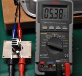
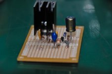
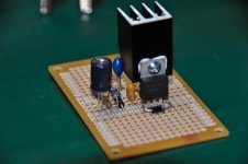
Here's my first version of the regulator built as per Regiregi's 1.1 schematic.
Seems to do the job pretty well... my benchtop DC voltage source only goes up to 32V but the regulator gives a steady 5.38~5.39 volts output between about 10 and 32 volts. I'll show the 'dark side of the board' once I have corected my silly mistakes and added suitable capacitance.
Don't hold your breath though, I am just a stupid flute maker with a soldering iron!
Many thanks to Regi for answering my daft questions without passing judgement!
Bill
Attachments
If you look at the schematic, it already has all the BOM inside it.Is their a BOM for this alternate shunt regualator?
You only need 1x LM317, 1x 1N4007 diode, 6x standard LEDs and 1x22Ohm resistor (which I think is an standard 1/4W, but someone may correct me).
It is a shunt regulator set at 40mA, which means that it will ALWAYS consume constantly 40mA. It will supply a max. current of 40mA. That means that all the current from that that the lightspeed is not consuming, will be dropped by the regulator.
It is set to 40mA because that is the totally maximum consumption of a lightspeed.
"..BTW.
For 5V from a 317:
a pair of LEDS totaling 3.7V to 3.8V substituted for R2 will give near enough the right voltage and will allow the 317 to perform better..."
I have a 317, and confused by your LED statement, could you please explain how a pair of LED's 3.7 to 3.8 can be substituted for R2?
Do LED's have a resistive quality? I thought a resistor was required in an LED circuit to prevent it from burning up?
LED calculator for single LEDs
Can you suggest part numbers?
Nice building, Bill. As long as you keep input voltage 2v over output voltage, you should be fine and stable. The higher the input voltage (while keeping the same output voltage), the more tolerant the PSU will be with input voltage variations.
I will explain myself: With an output of 5v, if you have an unstable input of 10v, which momentarily drops to 7v, the regulator will keep feeding 5v stable. If you were supplying it with 7v and hace a line drop of 3v, your regulator won't work for that time.
The bad side is that as you go up with voltage, you get more hot from the regulator.
Did you finally placed a 330Ohm load resistor? We will see how much big the heatsink needs to be when we have all mounted and connected...
Regards,
Regi
I can't understand what are you saying about the LEds, ppcblaster. My apologies.
Can you quote where come from your sentences? 🙂
Regards,
Regi
Can you quote where come from your sentences? 🙂
Regards,
Regi
From Andrew T's Post
"...Regi schematic shows Tantalum for all 3 capacitors. 1uF tant should work in the locations shown.
But there has been discussion in this thread and in many others of the failure reputation of tantalum.
In general the advise seems to be don't use them. At worst the advice I've seen is back through all your old builds and remove all Tantalum.
If you choose to not use Tantalum then follow the Manufacturer's advice for the decoupling caps.
BTW.
For 5V from a 317:
a pair of LEDS totaling 3.7V to 3.8V substituted for R2 will give near enough the right voltage and will allow the 317 to perform better.
__________________
regards Andrew T.............."
Update: MyRef_C Ultimate BOM Documentation v1.3
UPDATED:
This is the new release of the Documentation for this project. It aims to pack all the neccesary schemes, info, pictures and schematics to succesfully complete this Group Buy kit.
Changes in v1.3:
-Official main schematics: changed some displayed values to match to what comes with the kit.
-Official main schematics: Identification bottom-right label changed to more complete information.
Thank you very much to Geoffcooper for doing both changes.
MyRef_C_Ultimate_Documentation_v1.3.rar
Regards,
Regi
Its ALIVE!!
Holy smokes. First 20 seconds you could tell its awesome. I am honestly not trying to hype you guys up. It really is fantastic and not even any burn in yet!. I have only a few mV of offset. Will post a pic tonight after dinner.
Will start shipping tomorrow.
I have no heat on my Caddock heatsink right now but will check after dinner. I suspect it will be fine as confirmed by Caddock engineer. Will use the heatsink that Madisonears suggested since it just looks beefier than the second one I ordered.
I love building amps! I dont think I will be doing more group buys for amps though. This has been a major pain, more than I thought it would be. I see a group buy for a chassis in the future as thats easy and there is a major amp case designer down the street from me I have been talking to.
Anyway, thats months away and this needs to be finished. Guys GO TO EBAY and get yourself a Sonance Sonamp 260 case. Its perfect. I have the MYREF in it and another chip amp. It includes a mount for a toroid and room for a second. An on/off switch that does not allow pops. Perfect heatsinks already in place!
WOW this thing has nice bass!
Uriah
Here is the completed but ugly amp.
Picasa Web Albums - Uriah - Ultimate MyREF
Will tidy it up after done messing with all our little tests with opamps and resistors. God it sounds good.
One channel has a little noise, 60hz so its some induced humm. Probably grounding like last time. Will try grounding with alligator clips tomorrow to see what I can do to fix it.
Uriah
Uriah, I see you have the Obligatos off in the corner. Any chance of mounting those on the bottom of the boards?
I got my Obligatos today for the Pass B1 project. Kinda look like a pipe fitting, a nice pipe fitting.
I got my Obligatos today for the Pass B1 project. Kinda look like a pipe fitting, a nice pipe fitting.
Its ALIVE!!
Holy smokes. First 20 seconds you could tell its awesome. I am honestly not trying to hype you guys up. It really is fantastic and not even any burn in yet!. I have only a few mV of offset. Will post a pic tonight after dinner.
Will start shipping tomorrow.
I have no heat on my Caddock heatsink right now but will check after dinner. I suspect it will be fine as confirmed by Caddock engineer. Will use the heatsink that Madisonears suggested since it just looks beefier than the second one I ordered.
I love building amps! I dont think I will be doing more group buys for amps though. This has been a major pain, more than I thought it would be. I see a group buy for a chassis in the future as thats easy and there is a major amp case designer down the street from me I have been talking to.
Anyway, thats months away and this needs to be finished. Guys GO TO EBAY and get yourself a Sonance Sonamp 260 case. Its perfect. I have the MYREF in it and another chip amp. It includes a mount for a toroid and room for a second. An on/off switch that does not allow pops. Perfect heatsinks already in place!
WOW this thing has nice bass!
Uriah
Dude, I'm getting excited now!!! Thanks for the tip on the 260 case, been wondering what I was gonna' do on that part of it.
Thanks,
Treytexag
Did you said opamp rolling? Or are you referring to regulate it? 😀Here is the completed but ugly amp.
Picasa Web Albums - Uriah - Ultimate MyREF
Will tidy it up after done messing with all our little tests with opamps and resistors. God it sounds good.
One channel has a little noise, 60hz so its some induced humm. Probably grounding like last time. Will try grounding with alligator clips tomorrow to see what I can do to fix it.
Uriah
I think I will leave the obbligatos there near the inputs so I can play with other caps if I want to. I could have put them next to the boards. Under the boards might not have fit well in my case, but I didnt try either.
You do not need sinks that big. Thats what comes with that case.
Bill sent me some LM318 in metal hats. So I will try those. No other opamp rolling.
You do not need sinks that big. Thats what comes with that case.
Bill sent me some LM318 in metal hats. So I will try those. No other opamp rolling.
- Status
- Not open for further replies.
- Home
- Group Buys
- MyRef_C with Ultimate BOM