We did not plug the Rev_C in the main system.. Only the shop system.
And the shop SS Revelator 6.5's were the 4 Ohm version.
And the shop SS Revelator 6.5's were the 4 Ohm version.
color coded BOM and assembly instructions
there really is very little magic. The basic idea in stuffing the boards is to do it so that smaller lower lying things get done before bigger things that overshadow them for purely matters of convenience. So: all the little resistors first, then all the small caps. One suggestion that's been made is that putting in the very caps after you mount the amp chip because you might have a hard time otherwise to get the screw driver in there. For the soldering, if you don't have much experience, you might practice on something else first. Basic rule is to go in quick. Nothing too paranoid, but you don't want to be holding that iron against some part for a very long time since it is entirely possible to overheat it. I took some pictures during my assembly process which will give you some idea about general order. See http://picasaweb.google.com/schro20/FinalBuildOfRevCFromKit# (note how I did not mount the chip before I put on the big caps and promptly had a hard time with the mounting screw for the chip on the heatsink...) Important when mounting the chip on the heatsink is to ensure that you have perfect insulation (with the help of the nylon bushing) between chip and heatsink. Test this with an ohm meter to make sure. Very very important.
One thing to watch out for is the polarity on the diodes and the electrolytic caps. It's all marked but you need to pay attention.
peter
Dear Marc,marc brown said:I'm sure there were but I can't find them -- was there a post that gave assembly instructions or guidelines?
there really is very little magic. The basic idea in stuffing the boards is to do it so that smaller lower lying things get done before bigger things that overshadow them for purely matters of convenience. So: all the little resistors first, then all the small caps. One suggestion that's been made is that putting in the very caps after you mount the amp chip because you might have a hard time otherwise to get the screw driver in there. For the soldering, if you don't have much experience, you might practice on something else first. Basic rule is to go in quick. Nothing too paranoid, but you don't want to be holding that iron against some part for a very long time since it is entirely possible to overheat it. I took some pictures during my assembly process which will give you some idea about general order. See http://picasaweb.google.com/schro20/FinalBuildOfRevCFromKit# (note how I did not mount the chip before I put on the big caps and promptly had a hard time with the mounting screw for the chip on the heatsink...) Important when mounting the chip on the heatsink is to ensure that you have perfect insulation (with the help of the nylon bushing) between chip and heatsink. Test this with an ohm meter to make sure. Very very important.
One thing to watch out for is the polarity on the diodes and the electrolytic caps. It's all marked but you need to pay attention.
peter
Yes was the one with
2 white leads, ONE red, black, yellow and blue?
Not sure on the hookup. Had seen that pic in the comment but not quite enough detail to see the exact hookup.
Thanks again for any help.
2 white leads, ONE red, black, yellow and blue?
Not sure on the hookup. Had seen that pic in the comment but not quite enough detail to see the exact hookup.
Thanks again for any help.
Re: color coded BOM and assembly instructions
Thanks Peter. I've gotten all the small resistors and caps installed. I read up on capacitor markings so I'd get the polarity right. I've got a nice soldering station so I'm pretty confident that I didn't overheat any components. Four of the caps confused me for a bit. In most everyone's in-progress pics they look like dark red jelly beans but mine were little yellow boxes. I finally realized I had to carefully bend one of the pins to fit those guys on the pcb.
I'm thinking about installing one of the big caps on the back of the board so that it makes it easier to get to the 3886's mounting screw. Once I'm finished I'm nervous about powering it up for the first time. I'm sure things are in the right place but it's like starting up a rebuilt motor . . . . .
I'm looking forward to checking out some waveforms on my o-scope to see what sort of job the amp is doing. I'm also going to use the o-scope to help me mod an old Magnavox cd player.
😎
schro20 said:
One thing to watch out for is the polarity on the diodes and the electrolytic caps. It's all marked but you need to pay attention.
Thanks Peter. I've gotten all the small resistors and caps installed. I read up on capacitor markings so I'd get the polarity right. I've got a nice soldering station so I'm pretty confident that I didn't overheat any components. Four of the caps confused me for a bit. In most everyone's in-progress pics they look like dark red jelly beans but mine were little yellow boxes. I finally realized I had to carefully bend one of the pins to fit those guys on the pcb.
I'm thinking about installing one of the big caps on the back of the board so that it makes it easier to get to the 3886's mounting screw. Once I'm finished I'm nervous about powering it up for the first time. I'm sure things are in the right place but it's like starting up a rebuilt motor . . . . .
I'm looking forward to checking out some waveforms on my o-scope to see what sort of job the amp is doing. I'm also going to use the o-scope to help me mod an old Magnavox cd player.
😎
Re: monoblock:stereo
Using the same case tu run 2 trafos/2pcbs, will be good? or is better to go in separated case for each monoblock?
AndrewT said:Yes, a monoblock using the same components will always outperform a pseudo monoblock in a common case.
A pseudo monoblock should be able to outperform a pair of amps sharing a common case and transformer.
Using the same case tu run 2 trafos/2pcbs, will be good? or is better to go in separated case for each monoblock?
noodle said:Yes was the one with
2 white leads, ONE red, black, yellow and blue?
Not sure on the hookup. Had seen that pic in the comment but not quite enough detail to see the exact hookup.
Thanks again for any help.
Noodle-
This should be your hookup for ONE amp board with ONE transformer.
You can email me directly too. The email is in my profile here on DIYAudio.com and is enabled.
Attachments

Re: Re: color coded BOM and assembly instructions
You can post a picture and we can double check the placement of the parts..
I have a close up photo here:
http://picasaweb.google.com/troystg/Rev_C#
Click on the picture and then when it opens on the right hand side of it is a magnifying glass to "zoom in" on the PCB's.
marc brown said:
..... Four of the caps confused me for a bit. In most everyone's in-progress pics they look like dark red jelly beans but mine were little yellow boxes. I finally realized I had to carefully bend one of the pins to fit those guys on the pcb.......
You can post a picture and we can double check the placement of the parts..
I have a close up photo here:
http://picasaweb.google.com/troystg/Rev_C#
Click on the picture and then when it opens on the right hand side of it is a magnifying glass to "zoom in" on the PCB's.
Attachments
Re: Re: Re: color coded BOM and assembly instructions
There are a few other small differences (some of the power resistors, some relays; nothing major).
peter
Troy has the red jelly beans for C4/C5. Most people have small yellow boxes. This is because we got some parts from Brian.troystg said:
There are a few other small differences (some of the power resistors, some relays; nothing major).
peter
Re: Re: Re: Re: color coded BOM and assembly instructions
Hmmm.
Thats not good, I sure hope my second kit is the same as the first as I need 4 identical channels..
schro20 said:
Troy has the red jelly beans for C4/C5. Most people have small yellow boxes. This is because we got some parts from Brian.
There are a few other small differences (some of the power resistors, some relays; nothing major).
peter
Hmmm.
Thats not good, I sure hope my second kit is the same as the first as I need 4 identical channels..
Re: Re: Re: Re: Re: color coded BOM and assembly instructions
Hi guys,
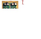
Here's a look at my build so far. album Zoom in to see detail. C4 and C5 are the caps I was asking about.
thanks,
Marc
troystg said:
Hmmm.
Thats not good, I sure hope my second kit is the same as the first as I need 4 identical channels..
Hi guys,
Here's a look at my build so far. album Zoom in to see detail. C4 and C5 are the caps I was asking about.
thanks,
Marc
Re: Re: Re: Re: Re: Re: color coded BOM and assembly instructions
Marc-
Yes, if Peter and Uriah say that is the correct value for those caps (C4 & C5) then your installation should work fine.
As mentioned, my first kit was a "trial" test fit and apparently had different caps but I am sure Peter and Uriah double / triple checked the parts before ordering / mailing and yours should work.
marc brown said:
Hi guys,
Here's a look at my build so far. album Zoom in to see detail. C4 and C5 are the caps I was asking about.
thanks,
Marc
Marc-
Yes, if Peter and Uriah say that is the correct value for those caps (C4 & C5) then your installation should work fine.
As mentioned, my first kit was a "trial" test fit and apparently had different caps but I am sure Peter and Uriah double / triple checked the parts before ordering / mailing and yours should work.
Re: Re: Re: Re: Re: Re: color coded BOM and assembly instructions
peter
They look like what I would expect.marc brown said:album Zoom in to see detail. C4 and C5 are the caps I was asking about.
peter
Re: Re: Re: Re: Re: Re: Re: color coded BOM and assembly instructions
Peter
Basically, if you followed the white paper labels on the caps everything should be fine. See the picture of the caps bag contents http://www.diyaudio.com/forums/attachment.php?s=&postid=1717114&stamp=1232334559schro20 said:They look like what I would expect.
Peter
Re: Re: Re: Re: Re: Re: Re: Re: color coded BOM and assembly instructions
Thanks Peter. I was just making sure for my own sanity -- this is my first DIY build.
schro20 said:
Basically, if you followed the white paper labels on the caps everything should be fine. See the picture of the caps bag contents http://www.diyaudio.com/forums/attachment.php?s=&postid=1717114&stamp=1232334559
Peter
Thanks Peter. I was just making sure for my own sanity -- this is my first DIY build.
Do your parts match? (They should!)
Brian Donegan donated leftover parts from the TP kits to this group buy. Most of those were resistors and we bought the exact same kind. So you won't see any difference. Some of those were capacitors (and we bought the exact same kind) and in some cases the newly bought types were the same values but different packaging. C4/5 comes to mind. There are also different versions of C3/8 because we just couldn't get enough of one kind (recall the horror stories of vendors flaking out on us). But in each case I made sure that a given pair has exactly the same components. (I packed them in pairs, so I am quite certain that I got that part right; you should check however if this is a major concern for your application). Across pairs I can't say for sure though I certainly tried to be mindful of that.
Please check now. Basically Uriah and I want to draw the big fat line underneath all of this and close out this GB. It'll be much harder to deal with issues after that point.
Thanks much to everyone!
peter
All pairs are matched. For those who ordered multiple pairs they *ought* to be matched across the pairs as well. Anybody who is concerned about this, PLEASE check now.troystg said:As mentioned, my first kit was a "trial" test fit and apparently had different caps but I am sure Peter and Uriah double / triple checked the parts before ordering / mailing and yours should work.
Brian Donegan donated leftover parts from the TP kits to this group buy. Most of those were resistors and we bought the exact same kind. So you won't see any difference. Some of those were capacitors (and we bought the exact same kind) and in some cases the newly bought types were the same values but different packaging. C4/5 comes to mind. There are also different versions of C3/8 because we just couldn't get enough of one kind (recall the horror stories of vendors flaking out on us). But in each case I made sure that a given pair has exactly the same components. (I packed them in pairs, so I am quite certain that I got that part right; you should check however if this is a major concern for your application). Across pairs I can't say for sure though I certainly tried to be mindful of that.
Please check now. Basically Uriah and I want to draw the big fat line underneath all of this and close out this GB. It'll be much harder to deal with issues after that point.
Thanks much to everyone!
peter
Re: Re: Re: Re: Re: Re: Re: Re: Re: color coded BOM and assembly instructions
Remember, these things were put together by a meat computer with meat servos, not one of those new fangled all metal robot devices. 🙂
Peter
Absolutely! These are good things to check up on and be certain. Better check twice than be disappointed later!marc brown said:I was just making sure for my own sanity -- this is my first DIY build.
Remember, these things were put together by a meat computer with meat servos, not one of those new fangled all metal robot devices. 🙂
Peter
The meat computer did a heck of a good job! I had no problems whatsoever building mine, and I'm very pleased with the results. I will post some listening impressions on the New My Rev C thread in chip amps forum.
Peace,
Tom E
Peace,
Tom E
madisonears said:The meat computer did a heck of a good job! I had no problems whatsoever building mine, and I'm very pleased with the results. I will post some listening impressions on the New My Rev C thread in chip amps forum.
Peace,
Tom E
I second that!!
I had NO problems with the channels I built nor do I expect ANY from the 2 channels yet to be built.
The only concern was that there might be different components in the 2 kits thus not making them 4 identical channels.
I can find out if there are any differences and order matching components if there are.
I still think the GB was 100% a success and appreciate all the work you two did!
vonfilm said:What size heat sink is needed for the My Ref RevC?
at least twice what National specify in the datasheet.
- Status
- Not open for further replies.
- Home
- Group Buys
- my_ref revC group buy (Mauro Penasa LM3886 design)