Do the 100v Cerafines fit since they are 2mm larger than the 50v ones?
I have used the 100V Cerafines on my Ver 1.72 boards and here are pictures of them on the Ver1. 8 boards. Don't know whether Dario has ever tried them but he did make the comment that the caps less than the 50V ones sounded different to him.
Cheers Pete
Attachments
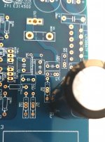
Hi Pete,I have used the 100V Cerafines on my Ver 1.72 boards and here are pictures of them on the Ver1. 8 boards.
yours seems a perfect fit but the position is for 16mm caps and 100V Cerafines should be 18mm... weird.
No, never tried others than 25V and 50V ones.Don't know whether Dario has ever tried them but he did make the comment that the caps less than the 50V ones sounded different to him.
Usually from 35V and up Cerafines have a different sound signature.
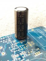
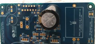
The Eagle PCB CAD object is for 16mm caps but you're right the circle is actually 18mm, never though about meausing it before...The printed circles at the C9 position are 18mm and 10mm Dario. The 100V Cerafines do measure 18mm in diameter (unless Parts Connexion has been selling me fake ones)
So, yes, 18mm caps are an option.
I have used the 100V Cerafines on my Ver 1.72 boards and here are pictures of them on the Ver1. 8 boards. Don't know whether Dario has ever tried them but he did make the comment that the caps less than the 50V ones sounded different to him.
Cheers Pete
Thanks Pete, pictures do show that they do fit quite nicely which is a very good sign since finding 50v ones are hard to come by.
Dario, what difference was made by installing the lower voltage Cerafines on the board?
They sounded not as rich and full, more distant from the control.Dario, what difference was made by installing the lower voltage Cerafines on the board?
Hi Dario,
Success! - pcb's received in post today! As others have previously commented, superb quality boards and also excellent SM soldering - needless to say it's evident you've done this work just a few times before!!
Many thanks indeed, now to get building and I'm looking forward to listening to a fantastic sounding amp ....
Kind regards,
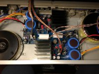
Hello to all the friends of the forum. i finished building my amp. this morning I started listening tests with the computer through my little dac smsl sd793II and Klipsh RB81 II speakers ... at 24bit / 96Khz it is spectacular ... I played Secret Story, incredible .... but this is not an amp. ..this is a magic box ... the Pat Metheny band materialized in my room .... I could touch the guitar. Thanks Dario. Although my version is basic, I still like it a lot.
Attachments
The design has been polished up. The original designer did not believe in audiophile parts.
He used generic parts.
He used zener based regulators for the input opamp. Also a 0.22 ufd input coupling cap.
Later he came around to discrete regulators, fast and soft rectifiers, and other tweaks. But he felt circuit design, operating points, layout, settling time, and clippping recovery were what was important.
He may have had it nailed. He knew way more than me. I use esoteric parts too.
Hi Dario,
So, some time ago I received from you, the 2 boards with the SMD very nicely soldered ;-) and the IsabellenHuete. So now, I wanted to start to order the components for the boards but after reading the documentation and the BOM from the google drive:
BOM in Google Drive
and then to check the Project: Industrial BOM + Evo A Mod without SMD parts
I realized of some discrepancy, with your BOM in the google drive, for example for R101/R102 you have 50R-0.5W-1% but in the Project in Mouser, they are selected 50R-0.1W-0.1% (Mouser Part:71-RN55C-B-50) and also it's happening the same for R104/R204 also in the spreadsheet is: 200R-0.5W-1% but in the Mouser Project is: 200R-0.1W-0.1%...
So the correct values are from the Mouser Project or from the Google drive? Or I am understanding this completely wrong what can be possible, since I am a very beginner
Thanks very much
So, some time ago I received from you, the 2 boards with the SMD very nicely soldered ;-) and the IsabellenHuete. So now, I wanted to start to order the components for the boards
but after reading the documentation and the BOM from the google drive:BOM in Google Drive
and then to check the Project: Industrial BOM + Evo A Mod without SMD parts
I realized of some discrepancy, with your BOM in the google drive, for example for R101/R102 you have 50R-0.5W-1% but in the Project in Mouser, they are selected 50R-0.1W-0.1% (Mouser Part:71-RN55C-B-50) and also it's happening the same for R104/R204 also in the spreadsheet is: 200R-0.5W-1% but in the Mouser Project is: 200R-0.1W-0.1%...
So the correct values are from the Mouser Project or from the Google drive? Or I am understanding this completely wrong what can be possible, since I am a very beginner
Thanks very much
I realized of some discrepancy, with your BOM in the google drive, for example for R101/R102 you have 50R-0.5W-1% but in the Project in Mouser, they are selected 50R-0.1W-0.1% (Mouser Part:71-RN55C-B-50) and also it's happening the same for R104/R204 also in the spreadsheet is: 200R-0.5W-1% but in the Mouser Project is: 200R-0.1W-0.1%...
So the correct values are from the Mouser Project or from the Google drive?
The parts you should buy are indicated on the "Order #" Coloumns, ignore the "Rating" one.
Those rating indications were the ones from the original through hole My_Ref but several parts changed to SMD and in any case the RN55 are military specs resistors that have the same power dissipation as 1/4W 'commercial' ones (that now are often indicated as 0.4W...).
Regarding R104/R204 the 1/2W rating is wrong, sorry, just fixed it in BOM.
Hello Dario,
I finished yesterday the amp, today I had massive testing
and I can just tell you that the sound is amazing, warm and vivid... I have by no means so good speakers (just some Polk audio s10) but the sound... man.... beautiful.... I just love it... Thank you very much for such a nice little thing I am non-stop listening to music for the last 10 hours
... beautiful.. !! You're welcomethe sound... man.... beautiful.... I just love it... Thank you very much for such a nice little thing
Enjoy your amp
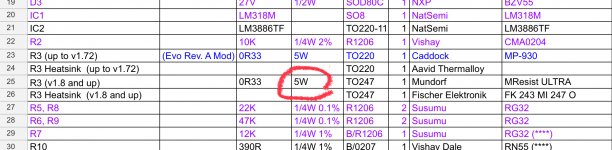
Hi Pete,Hi Dario, I just want to check something on the BOM…the Parts Connexion # is correct but the wattage description listed for the Mundorf Ultra is 5W, but the Mundorf we want is the 30W version, correct?
just searched for the part number in BOM and it gives that page:
Mundorf Resistor 0R33 MResist Ultra 30 Watt MREU30 Resistor
On the page is clearly stated that the resistor is rated 3W on free air and 30W with the specific heatsink.
On the My_Ref we need a 5W resistor so the MResistUltra with a small heatsink like the BOM suggested one will work perfectly.
The parts you should buy are indicated on the "Order #" Coloumns, ignore the "Rating" one.
Those rating indications were the ones from the original through hole My_Ref but several parts changed to SMD and in any case the RN55 are military specs resistors that have the same power dissipation as 1/4W 'commercial' ones (that now are often indicated as 0.4W...).
- Home
- Group Buys
- My_Ref Fremen Edition GB (14th GB)