Got It! I was under the impression replacement of only C9 was the consideration. Make much more sense now. 
C13 ( a non electrolytic) is removed as well.
The new topology is direct coupled.
Hi Andrew,
in reality I would still use C13; the servo goal, in my intentions, is only to deal with the amp's own offset.
Sorry Dario, but "the amps own offset" is a very broad/inclusive term to try to understand. Can you give a bit more detail? Are you using "Amp" to describe the LM3886 (or Lm318 as opamp) specifically?
Last edited:
Sorry Dario, but "the amps own offset" is a very broad term to try to understand. Can you give a bit more detail?
As most bipolar opamps the LM318 and LM3886 have a DC offset on their own, sometimes this offest can be trimmed by using balance pins.
Another source of DC offset, as KSTR has so well explained, is due to the different impedance seen by the inverting and non-inverting inputs.
This is what I call 'own offset'.
C13 ( a non electrolytic) is removed as well.
The new topology is direct coupled. That's why the DC servo and the offset detection and speaker protection is required.
For full DC coupling (i.e. both C9 and C13 removed), we'd probably need the servo to be able to handle a pull range of a few volts at the input. As things stand, C13 is retained, allowing the servo to handle the simpler task of just nulling out the offset generated by the opamp and chipamp - which would typically be not more than a 100 mV or so, referenced to the input.
This would remove C9 (a large electrolytic), while retaining C13 (a smaller and more linear film cap). Furthermore, C13 can be lowered from ~2.2uF to ~0.22uF while still retaining a lower corner frequency in the region of ~10 Hz. A lower-valued C13 potentially allows higher quality film caps (e.g. PTFE) to be used in approximately the same space.
Linux, that would explain the very high reduction ratio of 120k:390r
The pull range for +-15Vdc opamp supplies is ~ +-45mV of error correction. Probably more than plenty.
The pull range for +-15Vdc opamp supplies is ~ +-45mV of error correction. Probably more than plenty.
Last edited:
Just noticed that C9 is not shown in post1
We need a location so that new readers know what is being discussed.
Good idea, I've updated the opening post with a link to the schematic. 😉
Linux, that would explain the very high reduction ratio of 120k:390r
Yup, exactly. We could go lower to say ~10k for the injection resistor, thus increasing the pull-range, but that also makes the post-servo LPF capacitor more "visible" to the feedback network (and introduces another pole in the forward transfer function).
It's not a show-stopper, but will require more analysis for stability and also a higher-quality post-servo filter capacitor in the T-network. I think something like 2k2-3.3uF-22k may be workable.
For full DC coupling (i.e. both C9 and C13 removed), we'd probably need the servo to be able to handle a pull range of a few volts at the input. As things stand, C13 is retained, .......
As Andrew often mentions, (hope I have this right) the protection function between stages actually requires just one cap - either on the sending stage OR the receiving stage. If that's correct, would guaranteeing the sending side provides that protection allow for a more simplistic servo design? I understand that's somewhat risky with the many possible sources, but I am feeding the FEs directly from a DAC that doesn't appear to present any challenge to either the MyRefs or my descrete (Pass) builds.
It's obviously one of those "Use at your own risk" methods, but again could that (protection at the source output only) simplify the servo design?
Last edited:
It's obviously one of those "Use at your own risk" methods, but again could that (protection at the source output only) simplify the servo design?
I think it's safer to use a DC blocking capacitor on the Amp (i.e. receiving side), because we often tend to switch sources (some of which may or may not have an output DC blocking cap) into an Amp.
The DC servo design is also simplified by retaining the DC blocking cap at the input of the amp.
......The DC servo design is also simplified by retaining the DC blocking cap at the input of the amp.
Understood - Time out has expired 😀 Thanks Guys - good and very helpful information !
bcmbob, does your DAC have its own capacitor at the output?
And from earlier post:
Each opamp generates its own offset and the offset of the LM318 is inverted and amplified by the LM3886, then returned to the input of the LM318, only then is it blocked by C9 to unity gain.
As I understand it the voltage gain of the LM3886 is influenced by the connected load. If this is correct then both opamps have variable gains and when C9 is not used, a not easily to predict offset is then the result.
Last edited:
Hi Mark, I'm using the new Subbu/JP V3 almost exclusively now. You can see the layout in photos (output at lower-right corner, second pic) in the first post of the build thread.
However, after I posted I did realize for a higher SPL I sometimes add a JC-2 or the O2 pre just for the discretes. The FEs need attenuation only (PC drivers on Direct Sound). Works beautifully, but as Siva says, probably better to protect and not to assume
However, after I posted I did realize for a higher SPL I sometimes add a JC-2 or the O2 pre just for the discretes. The FEs need attenuation only (PC drivers on Direct Sound). Works beautifully, but as Siva says, probably better to protect and not to assume
Last edited:
Each opamp generates its own offset and the offset of the LM318 is inverted and amplified by the LM3886, then returned to the input of the LM318, only then is it blocked by C9 to unity gain.
As I understand it the voltage gain of the LM3886 is influenced by the connected load. If this is correct then both opamps have variable gains and when C9 is not used, a not easily to predict offset is then the result.
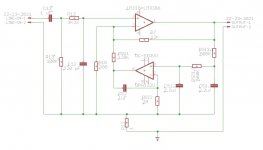
At DC, C9 has infinite impedance and then the feedback branch (after thinking of LM318+LM3886 as a single opamp) has only the R12 resistor (apart C10 feedforward capacitor & zener diodes to avoid LM318 spiking... but they do not count in normal operation and DC signals).
Then, it acts as a "buffer opamp", with unity gain.
Nevertheless, C9 is always inserted and "seen" by the audio signal. That's the reason why its removal should be beneficial to the sound.
About the removal of C13, as linuxguru wrote, it's not safe to remove it because, after years, amplifiers get connected to different sources 😉
Moreover, C13 helps to keep the offsets more controllable. Do not forget that Mauro Penasa pushed a lot the polarization and balancing of LM318 (we already stated that, most probably, the unbalancing of input impedances was made on purpose). 🙂
Daniele
It was already suggested to connect the servo control to the speaker DC detection circuit or regulating the servo sensitivity depending on the offset to be corrected.
If the current My_ref can be used without C13. The servo version should also be able to.
If the current My_ref can be used without C13. The servo version should also be able to.
But it's a google doc.
How do we scale it, so that we can read it?
Click on the down arrow, you should be able to download the original PDF
Attachments
Click on the down arrow, you should be able to download the original PDF
Alternatively, click on the + & - symbols in the adjacent magnifying glasses.
Geoff
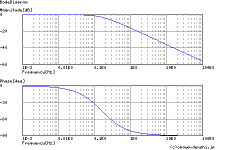
I asked if the Fc = 0.16Hz is low enough.
Apparently it's not:

(image from this calculator)
But the graph is for a single LP filter...say the input filter of the servo.
The integrator itself with his feedback cap CS2 and RSI2 resistor isn't a second LP filter that should increase the filtering slope?
Also the high value of RSO1 should reduce further the AC (and noise from high value input resistors) content by near an order of magnitude using the 10 to 1 rule of AN-1192, if I understood correctly the servo gain is related to the ratio of R7 and RSO1.
Also the higher is RSO1, the less the amp gain is modified, since RSO1 is in fact in parallel with R10.
At the same time we can't set a too high RSO1 value since it determine the pull range that must be adequate for the worst 'own' offset of the LM318+LM3886 combo.
Is this correct?
In addition... if the filtering it's still not enough why not moving the T-filter at the input stage of the servo?

Shouldn't this further increase the slope and simplify DC-servo's opamp work?
Apparently it's not:
(image from this calculator)
But the graph is for a single LP filter...say the input filter of the servo.
The integrator itself with his feedback cap CS2 and RSI2 resistor isn't a second LP filter that should increase the filtering slope?
Also the high value of RSO1 should reduce further the AC (and noise from high value input resistors) content by near an order of magnitude using the 10 to 1 rule of AN-1192, if I understood correctly the servo gain is related to the ratio of R7 and RSO1.
Also the higher is RSO1, the less the amp gain is modified, since RSO1 is in fact in parallel with R10.
At the same time we can't set a too high RSO1 value since it determine the pull range that must be adequate for the worst 'own' offset of the LM318+LM3886 combo.
Is this correct?
In addition... if the filtering it's still not enough why not moving the T-filter at the input stage of the servo?
Shouldn't this further increase the slope and simplify DC-servo's opamp work?
Attachments
Last edited:
- Status
- Not open for further replies.
- Home
- Amplifiers
- Chip Amps
- My_Ref Fremen Edition - Collaborative DC-Servo design