Salve George! Is it possible to graph your findings from 0R to above 1K so we can see what that looks like? Or, is it a bit complicated to derive your findings from the graph and it's more based on a learned estimation?I have done an optimization: a sweep of values from low to high resistance and looking at the phase margin change. Where the rate of change slowed down I 'had drawn a line'. Also, there is a limit to this value: the higher this series resistance, the more noise we inject so tried to apply the minimum needed. 1 kohm came up like a good tradeoff.
Ciao, George
Grazie, Pete
Pete,
Ok, I sat back and tried to find a more directly perceivable demonstration of the mechanism , the effect of this resistor.
I can put here also the loop gain curves, but that (while showing the full story) might be more delusional, one has to dig into to "see" the behaviour.
But with slight tweaking of the circuit it is possible to 'drive' it into marginal instability, and in that circumstances the effect of this series resistor jumps out more evidently..
Again: in general the effect is that of shifting the system response to greater phase margin, and so better stability.
But in that particular, border line case when the original setup is in the state of marginal stability, the otherwise subtle effect of this resistor becomes more dramatic.
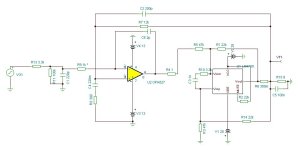
So let me put here the scheme - one can notice those slight tweaks for de-stabilizing de amp: feedback compensation cap shifted from 150pF to 200pF; local feedback for the OPA827 decreased to 2pF; the Output loaded with 100nF. (note that only small changes are enough..)
So, in the following test sequence only the input series resistor, R9 value will be swept from 1,2kohm down to 0,1ohm, the rest is left invariate.
The input signal is a 10kHz square wave, 50nsec rise time.
Ok, I sat back and tried to find a more directly perceivable demonstration of the mechanism , the effect of this resistor.
I can put here also the loop gain curves, but that (while showing the full story) might be more delusional, one has to dig into to "see" the behaviour.
But with slight tweaking of the circuit it is possible to 'drive' it into marginal instability, and in that circumstances the effect of this series resistor jumps out more evidently..
Again: in general the effect is that of shifting the system response to greater phase margin, and so better stability.
But in that particular, border line case when the original setup is in the state of marginal stability, the otherwise subtle effect of this resistor becomes more dramatic.
So let me put here the scheme - one can notice those slight tweaks for de-stabilizing de amp: feedback compensation cap shifted from 150pF to 200pF; local feedback for the OPA827 decreased to 2pF; the Output loaded with 100nF. (note that only small changes are enough..)
So, in the following test sequence only the input series resistor, R9 value will be swept from 1,2kohm down to 0,1ohm, the rest is left invariate.
The input signal is a 10kHz square wave, 50nsec rise time.
Attachments
Last edited:
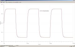
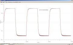
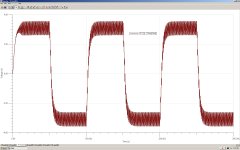
So here it is, the output response to the input square signal while sweeping the value of R9 from 1,2kohm to zero ohm (0,1ohm)
Attachments
-
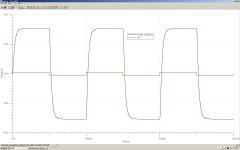 OPA827_Rser_1,2kohm_2pF_200pF_100nF.JPG99.3 KB · Views: 128
 -
 OPA827_Rser_900ohm_2pF_200pF_100nF.JPG96.4 KB · Views: 125
 -
 OPA827_Rser_600ohm_2pF_200pF_100nF.JPG104.5 KB · Views: 117
 -
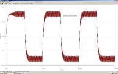 OPA827_Rser_300ohm_2pF_200pF_100nF.JPG147.3 KB · Views: 120
 -
 OPA827_Rser_0,1ohm_2pF_200pF_100nF.JPG150.7 KB · Views: 125

Thank you for this George. I understand you were trying to demonstrate the stabilizing effect of R9 and I appreciate this exercise and your efforts. But, to artificially create an unstable situation to show the effects of the addition of another component is, in my mind, a bit misleading with reference to viewing the "already stabilized" build as would be done normally. One graph is needed for proper comparison...feedback compensation cap back to 150pF?, local feedback for the OPA827 back to 5pF?, the output loaded with whatever is normal and R9 set to 0 -0.1R. In this "normal stabilized stock" build are we viewing a graph that resembles your 600ohm graph or your 900ohm graph?
With appreciation,
Pete
With appreciation,
Pete
okkey.. now just don't forget that, for example for the OPA827 'normal condition' (original suggested value) was not 150pF but 100pF. Not by accident.
The same for OPA828. ~70pF suggested.
So these conditions can then be relaxed to 150pF 'standard' value for compensation, with "R9" added.
The same for OPA828. ~70pF suggested.
So these conditions can then be relaxed to 150pF 'standard' value for compensation, with "R9" added.
Just so as to be very clear: in 'normal conditions', for each particular opamp, configuration, (always slightly different) the square wave test above !Obviously looks like the best one of the series, R9=1,2kohm.. That was the target function of the whole operation, to obtain a stable non resonant response..
Hello George, the polarity on both channel are fine, on the channel that the relay did not click and no LED on I found one leg of the 1nf cap was touching the chassis and resistor r11 is open if measure voltage across it is 24.3 but when measure for resistant nothing, no ohms, but then checked voltages through the board and this is what I got: T101=14.3 T201=-14.3 R224=-0.6 R104=0.6 D105 =-13.7 D205=-13.7 IC101=14.3 34.6 IC201=-14.3 -34.2 R101=1.24 R201=1.24 R11=UL for the other channel that was working but music very very low now is not working but checked R11 is fine or I think is fine it is R11=1.2ohms these resistors from mouser are 1ohm 1% don't know if that measure is fine for the amp. ThanksCheck three times the polarity of the input signal.. with respect to the onboard GND...
Soo.. last time I was optimistic, from your description it looked like a functional setup in the previous test.. So something important had to have happened in the transfer.. 🙄
If You measure 1,2ohm on the 'good' R11 that sounds quite ok, yes.
Unfortunately, on the other hand a burnt out R11 could mean more things: could mean hope, that once R11 restored that was all ... but as well could be that the burnt R11 is just a side effect of more damages.
exchanging R11 definitely worth it, in a worst case it burns again..
your power supply voltages seem to be OK, though. at least.. and on that channel.
it would be more information to see the output voltage on the not working amp (between PGND faston stand and 'positive output'..
also pin 6 of the LM318 chips
Ciao, George
Thanks George, I appreciate your help, going to check output voltage and after that need unmount the board to replace R11 and pin 6 of the LM318, how do you check that one , ground probe of the meter to any ground point and positive probe to pin 6? Another Am very positive that all resistor value were correct before I soldered them but when I measure them on the circuit don’t see the the resistor value, is because they are in the circuit? I think is time to unmount the board and do a serious troubleshooting, I don’t know how but going to doing anyway, good luck for me. Thanks George.
yes, as you say multimeter '-com' to PGND, or HSGND, -red on pin 6. (be careful not to short the opamp pins with the probe tip. ) The opamp output on a functional FE board should stay at 0V. (with no input signal). Yes, only rarely one could test resistance on a circuit board, the presence of the active chip input / outputs pull off the values.
but you could measure resistances in both working / not working channels and have a comparison - they should measure at least ~equal, close values at both channels, though not nominal values.
I would start with replacing R11.. if that channel come up, that could be a reference for the other channel. If not coming up, consider the block exchange of both lm318 & lm3886.. painful, but just resolves any further doubts and delays..
if you replace only one of them, the other still can kill the substitute.. not g8ven, but could happen.
Then, for example control the zener diode polarity in klipper section, in the low volume unit..
Good luck, George
Thanks George, your awesome, again thanks for the tips and information but to replace the amp is very sad and stressful there is no way to found that one, imagine to get the ones I’m using I paid a fortune but that is not your fault. Thanks
I think there is good hope that the 3886 chips are still ok.. just wanted to tell my experience that a useful shortcut to the problems in the happy past (with 3886 at 5/6 € ) was just go and restart with a 'clean page'.. and all this only because of the event of R11 burnt, not totally innocent accident.
Wish You all the best!
Wish You all the best!
george, is 0.00 v, good or bad?it would be more information to see the output voltage on the not working amp (between PGND faston stand and 'positive output'..
it's good. Supposed that power supply is 'ON', definitely a good result.
Try to inject some signal, like 400Hz 100mV rms, You should see 3,1Vrms on the output, between PGND and output faston connection. You could detect it with your DMM, in 'AC' Volt mode..
Try to inject some signal, like 400Hz 100mV rms, You should see 3,1Vrms on the output, between PGND and output faston connection. You could detect it with your DMM, in 'AC' Volt mode..
But anyway, already the 'zero volt' output + the fact that the relay does not click means that the relay sense circuit is off, somewhere
Whoop, this board is stubborn try to unsolder R11 without flux took me like 2 hours until I give up for the night got to much stress going to try tomorrow using flux
Klip it!! yep that is a difficult position.
My thumb role is: clip the res, so it is a bit easier to remove the pin residuals from the hole.
Second thumb role: it could re-happen in the future. So I do not even remove the pin residuals, just solder the new R11 onto the pads from below.. next time no pain..
My thumb role is: clip the res, so it is a bit easier to remove the pin residuals from the hole.
Second thumb role: it could re-happen in the future. So I do not even remove the pin residuals, just solder the new R11 onto the pads from below.. next time no pain..
- Home
- Amplifiers
- Chip Amps
- My_Ref Fremen Edition - Build thread and tutorial