heh.. post #5000....
Sorry, Dario, that milestone should have gone to You!!! 🙂 🙂
Sorry, Dario, that milestone should have gone to You!!! 🙂 🙂

Wait a minute! 🙂
You mentioned only two changes, the LM318 and C9..
The correct implementation -or at least 'classic' with LM318 was originally with C9, yes, but also without that 1kohm resistor and instead R39 (470k), R43(22k), C34 (27pF) re-implemented.
So how does your build looks like now, what of these is there what is not..
Good point, clear as mud....99% sure this is what I have at the moment Joseph! Built to v1.5 BoM plus your 1K mod.
Ok, thank You Simon! That's correct, a valid config, very probably working well (I mean also technically) - it's long overdue for me to try it too..🙂
Ciao George!First of all: Simon, thanks for your report!
I can only quote your observation. And I'm happy that it was not me, that I stayed put about the sound. And still you found something similar to me..🙂
Dan, let me reassume:
Original suggested config for OPA828:
extra 5pF accross pin2-pin6, 68pF main compensation cap (C32),
R39, R43, C10, C34 eliminated
New modified compensation for OPA828:
extra 5PF accross pin2-pin6, 150pF main compensation cap (C32), 1kohm inserted between C12(220pF input cap) & pin2 (-IN)
R39, R43, C10, C34 eliminated
That intermediate solution Simon talked about was just a temporary, intermediate 'trial' solution from his part
All the best, George
So are you recommending that we who built our boards with the original 828 compensation (and love what we hear) should implement this new modification for 828? So, I'd just have to change the cap at C32 to a 150pF (polystyrene or silver mica or AMCH) and use the 1K SMD resistor between C12 & Pin2 (after cutting the trace)?
Grazie, Pete
Dear Pete,
Yes, I do suggest to try this. It's a more correct approach in the compensation for this chip for sure.
Yes, I do suggest to try this. It's a more correct approach in the compensation for this chip for sure.
George...any thoughts about this new compensation resistor's use in any of the other opamp variations? I have a build using ADA4627 so there is already is a 5pF across pins 2-to-6 and 150pF at C32.
Grazie, Pete
Grazie, Pete
Hello, I'm in the final step to finish my amp, actually connected it to power and the relays click and led's light on but planning to use resistor to dim the led that they are going to be set at the front panel, can these resistors be a problem for amp and what would be the value for these resistors, is 20k a good one? thanks in advance.
Pete,George...any thoughts about this new compensation resistor's use in any of the other opamp variations? I have a build using ADA4627 so there is already is a 5pF across pins 2-to-6 and 150pF at C32.
Grazie, Pete
It was a good question so I digged out the old simulations with the ADA4627.
With the configuration of 5pF local feedback across pin 2-6, and 150pF compensation cap what the 1kohm series 'damping' resistor does is shifting to a ~30% lower point the unity loop gain crossing frequency so we gain ~30% more phase margin, which is only good.
The same for OPA827, which turns 'operative' with 150pF main compensation cap in the loop (instead of 100pF suggested earlier..)
This series resistor is just letting the 5pF local compensation cap work as designed..
Also, in the past I had tried a series of BJT input opamps, with which I always had to struggle a bit.. with some extra added compensation help in different points in the circuit.
Now I had tried with the 1kohm inserted, and this way the 1kohm, 5pF, 150pF 'triad' seems to work smoothly, no need of anything else.. (C9 needs to be in place, obviously)
Just tried again AD797, ADA4898, OPA1622 all work smoothly.
OPA1611 does not, as Tom has pointed out many times..
caveat: All this in simulation!!
Though I have to say simulation had shown very good predictive power up to now, in my case.
Ciao, George
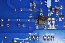
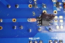
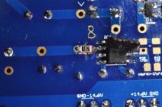
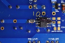
Wonderful George! The 0805 size SMDs appear to fit well but they are only 1/8W If that really matters at this position. Here are the steps I took to mount a 1K 0805 SMD resistor onto the board.
On to the second board...hope this works.
- The board before any work was done
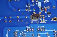
- Using solder wick, desolder the lead of the capacitor and clean up
- Using a new scalpel blade, scrape away the lacquer coating over the copper trace
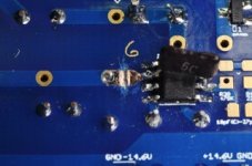
- An 0806 size resistor in position
- An 1206 size resistor for comparison
- Using a flat head, small jeweler's screwdriver (scalpel wasn't working too well) carefully scrape away a straight line in the copper track and clean with alcohol.
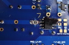
- Position the SMD resistor appropriately
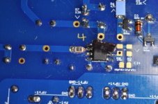
- After adding a small amount of flux to the capacitor lead side, use a conical tip on your soldering iron with a small ball of solder and tack the SMD in place on the capacitor side. Don't worry about appropriate solder flow right now.
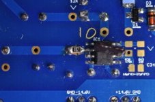
- Add flux paste to opamp side of resistor area. Heat with the conical tip and flow in solder (thin solder is best to avoid a mess).
- Add flux paste back onto left side area around cap lead and use thin solder to create a good joint.
- Clean up rosen on solder area.
On to the second board...hope this works.
Attachments
-
 FA9EB446-FA80-464A-8222-1800E0AA632A.jpeg25.4 KB · Views: 125
 -
 178EF14C-5D92-4A17-B62A-7DAFAD428D83.jpeg26.3 KB · Views: 125
 -
 2E62CBF3-31C0-48CB-A1E4-95656D9B736D.jpeg27.3 KB · Views: 121
 -
 9A642A9D-C011-4C22-8E05-B3B8E7C2CFD2.jpeg25.1 KB · Views: 118
 -
 7FEDB333-2FE1-47E0-A761-3AE088BA92D6.jpeg24.5 KB · Views: 116
 -
 13D79FC6-9E19-44E2-B106-B8B280BA7AB9.jpeg21.4 KB · Views: 122
 -
 273EB726-01EC-46B7-885A-921B9DC36803.jpeg22.1 KB · Views: 114
 -
 74E710D9-82BD-4AAB-B76E-BE345633484E.jpeg22.9 KB · Views: 121
 -
 6D60A159-B7BC-4D0E-8893-EC4189F6C669.jpeg22.8 KB · Views: 117
 -
 9EE2D252-0018-4260-AFA3-4B6C15331302.jpeg23.5 KB · Views: 122
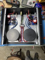
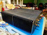
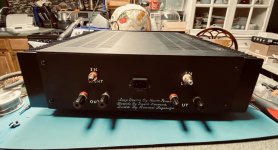
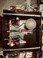
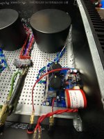
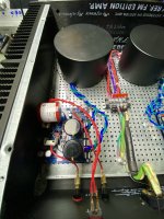
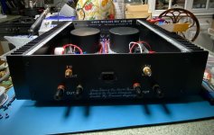
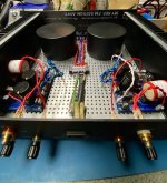
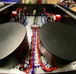
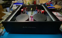
Well today is sad day is frustrating is stressful because when I started building the amp said to myself this have to work the first time that is power on, check all components, the position the values and so on, then finish it , power on and …. Relays click led’s on check all voltages they were fine, dc offset very low,almost perfect, then said is time to move amp upstairs to the music room to play some music and only one channel has sound but very low the other Chanel relay did not click obvious no sound now going to unmount the boards to check better for voltages, so what is the first thing to check , I appreciate in advance all your help you can give me. Some pictures of the building
Attachments
-
 71191B70-84F1-44A1-B8AB-E77F7D22CCEE.jpeg512.2 KB · Views: 114
 -
 F0AA5B13-0DB6-471E-8687-7E5EDAC8B9EB.jpeg258.3 KB · Views: 116
 -
 E1F0B523-635D-4C65-8157-347EA6D41227.jpeg516 KB · Views: 121
 -
 89EED44D-3F2E-4E8F-A88B-EF3684E4B5A0.jpeg544.1 KB · Views: 144
 -
 73C1C46B-D3DA-46F9-92CF-D7357811B163.jpeg529 KB · Views: 124
 -
 8A33BC8D-9EFC-4410-8C4C-7803C06D5153.jpeg334.3 KB · Views: 108
 -
 2FB55ACE-6532-433E-821C-CABE62CF9307.jpeg579.3 KB · Views: 112
 -
 5D363EAD-D24F-4EAA-B311-0A0D2A1B85AB.jpeg535 KB · Views: 132
 -
 CB17B11D-0F37-41B3-9B9F-B5508FBEE279.jpeg328.5 KB · Views: 107
let me explain: given that You saw correct behaviour, relays clicking into 'enable' plus measured principal voltages ok on the boards - that indicates the assembly is basically OK.
Now a typical error is that you connect your input cable to the input pin header - inverted..
Look up carefully where GND is connected on the onboard two pin connector, and control if that pin is actually connected to the RCA outer shell.. That is, use a multimeter and check for low resistance between onboard Signal Gnd and RCA outer shell. Like 1ohm or less
Control for both channels, independently of how they behaved in error.. (and I would not unmount anything, until this is cleared up safely)
Ciao, George
George: in that original illustration first showing the insertion of the 1K compensation resistor (post #4959) where did you arrive at the value of 1K? I'm trying to understand the logic of it all.attention, the above sketch is just for illustration showing the place where to insert that extra resistance. Would like to underline again, all the rest of modifications are valid & necessary, as before (in the case of applying that specific opamp)
Thanks,
Pete
I have done an optimization: a sweep of values from low to high resistance and looking at the phase margin change. Where the rate of change slowed down I 'had drawn a line'. Also, there is a limit to this value: the higher this series resistance, the more noise we inject so tried to apply the minimum needed. 1 kohm came up like a good tradeoff.
Ciao, George
Ciao, George
- Home
- Amplifiers
- Chip Amps
- My_Ref Fremen Edition - Build thread and tutorial