Jac, but in this case the feedback net terminated directly to ground, not to the 1 Ohm resistor (R 11). By this way the input net and the feedback net won't see the same potential. Is that correct? In all the Dario schematics the feedback net terminates on R 11, not directly to ground (I admit, I'm a little bit confused about it).
Probably I'll go populating the C9 indicated place, it's quite a pity, the unmarked place should have been perfect to try some bypass small capacitor in parallel with the big electrolytic one...
Massimo,
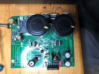
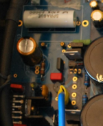
You got me curious, so I pulled out my old v1.0 boards. The picture shows my board built in the "resistor first" and using older BOM components. Sorry for the poor lighting.
A bit of explanation on grounds. Audio ground is the ground plane on the top of the pcb. This is the ground that C9 connects directly to in the "resistor first" configuration. The Audio ground is still isolated from the Power ground by R11, 1 Ohm. Power ground is the ground plane on the bottom of the pcb. So, "resistor first" and "capacitor first" are the same, both isolated by R11.
As for bypass caps, there was a later version that had a place for bypass caps, but at this early date, Blackgate caps were easily available and don't really need a bypass cap. If you want to try a small bypass cap, you might be able to solder it to the C9 terminals on the bottom of the board.
Attachments
googling because 100uF c102 and c202 wasn't in the BOM (and I didn't purchase them... :-() I've found another thread of a audio friend (Rom vise) who used a board exact like mine one, he mounted the RC net exactly as you indicated, Jac, now the confusion is total... wich kind of solution I have to apply? He leaved unpopulated c102 and c202, is it correct?
Attachments
Let's start with C102 and C202. Leave them unpopulated. The positions were added to allow for extra stability of the regulated power supply (LM318), but we have never needed them.
It is completely OK to continue on the "capacitor first" solution. If I remember correctly, all of Mauro's boards and Dario's 1st prototype and Release Candidate boards were all "capacitor first". The amp will work correctly and sound just fine.
You have both options on the v1.0 board because "resistor first" was being experimented with and no one choice had been made. The consensus, after experimenting, was that the "resistor first" sounds a bit better. If you removed R10 and changed to "resistor first", you would be the same as later builds, but it is not necessary. Later versions only have the "resistor first" on the pcb.
For an idea of the difference between the two, please read posts 1362 -1366, page 137 of the My_Ref Fremen Edition - Beta Build/Fine Tuning thread. Of course, the BOM has changed quite a bit, so the difference may not be the same for your build.
..this is a GREAT help!! thank you a lot! I didn't find a black gate for C9, maybe I'll try some little capacitor bypass, even if I have to say that often I wasn't very happy with the sonic result of this solution, sometimes it discovers some upper harmonics, but the overall sensation is of sometimes confused and "mixed", something not completely coherent.
Basically I find more pleasant a little bit of lack (or hided) informations vs. complete information with some little incoherency here and there, my brain works better filling spaces instead of correcting them.
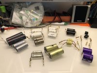
I'm also prosecuting with my insane idea about a self-made power resistor based upon thick film parallel resistor. The idea is to sandwich them between two silicone (with both thermal and damping function) thermic pad and two 3mm thick little titanium strips. I choose titanium because for my taste it "sounds" better, I always like the titanium sound of hard dome speakers, while hate aluminium ones and I'm not moved by copper ones.
Material is on the way (I think I'll wait about two months...) I'll keep you informed if interested
Massimo
Basically I find more pleasant a little bit of lack (or hided) informations vs. complete information with some little incoherency here and there, my brain works better filling spaces instead of correcting them.
I'm also prosecuting with my insane idea about a self-made power resistor based upon thick film parallel resistor. The idea is to sandwich them between two silicone (with both thermal and damping function) thermic pad and two 3mm thick little titanium strips. I choose titanium because for my taste it "sounds" better, I always like the titanium sound of hard dome speakers, while hate aluminium ones and I'm not moved by copper ones.
Material is on the way (I think I'll wait about two months...) I'll keep you informed if interested
Massimo
Please keep us informed. Experimentation is fun and you never know what will work until you try.
Jac
power supply arrangement
so, I'm at the power source... I'd like very much to use an old power supply arrangement, with great quality and looking, but it run with 39,2-0-39,2 V output, that is dangerously near to the LM3886 limit.
I'd can smooth it down with a pair of diodes in series, so the voltage should be 37,8-0-37,8 V... maybe still too high for a safe operation area?
Way too high
I bought a pair surplus transformers that were labeled as 24 volts. Canadian manufacturer. Got 37.5 volt rails.
FE ran hot even idling. Got scared and replaced with 24 volt Chinese. Now have 34 volt rails. The FE seems happier.
The voltage range for the LM3886 is too wide. Add five bolts to lower and subtract five from the upper.
The FE actually sounded nice with 37.5 volt rails. Never pushed much power to trigger SPIKE.
so, I'm at the power source... I'd like very much to use an old power supply arrangement, with great quality and looking, but it run with 39,2-0-39,2 V output, that is dangerously near to the LM3886 limit.
I'd can smooth it down with a pair of diodes in series, so the voltage should be 37,8-0-37,8 V... maybe still too high for a safe operation area?
I bought a pair surplus transformers that were labeled as 24 volts. Canadian manufacturer. Got 37.5 volt rails.
FE ran hot even idling. Got scared and replaced with 24 volt Chinese. Now have 34 volt rails. The FE seems happier.
The voltage range for the LM3886 is too wide. Add five bolts to lower and subtract five from the upper.
The FE actually sounded nice with 37.5 volt rails. Never pushed much power to trigger SPIKE.
Use this if you want to keep the transformer :https://www.diyaudio.com/forums/pow...sy-capacitance-multiplier-79.html#post6161883
Or 2 of the lm338
Or 2 of the lm338
thank you for the suggestion, it seems particularly interesting the Juma's Easy-Peasy Capacitance Multiplier, I can easily put it before the PCB supply rail due to the particualr shape of the box I'd like to use. The 4V drop down version should be perfect for me (i'll go with some make-up to the old box...)
Attachments
![P00415-104124[1].jpg](/community/data/attachments/749/749268-c2fb2dc0a514e05075f7c58d5f069164.jpg?hash=wvstwKUU4F)
Just a question: can I lower down the first capacitor before the capacitance multiplier (e.g.4700uF)? the next10mF in the pcb should be good enough to filter residual ripple
so, I'm at the power source... I'd like very much to use an old power supply arrangement, with great quality and looking, but it run with 39,2-0-39,2 V output, that is dangerously near to the LM3886 limit.
I'd can smooth it down with a pair of diodes in series, so the voltage should be 37,8-0-37,8 V... maybe still too high for a safe operation area?
Please consider how much heat that diode will be dropping and how hot it will get. If you do this it's probably best to use TO247 or similar so you can attach to the chassis or heatsink. Diodes generally drop around 1.5v so it's very possible that when you are blasting away you could have a diode shedding a watt or more of heat depending on a lot of variables. One watt in a tiny package can get super hot.
Any way you do it I think you still need to connect the my _ref Fremen board to ac for the protection section .
Last edited:
I don't know anything about the cap multiplier, so I can't help here. But I had to comment on the "box" That is a thing of beauty. True art. I wouldn't have ever dreamed of something like that, much less made it. Congrats.
Jac
Jac
Have you used a good input cup ?Today I did the big step in changing the opamp and installed OPA827, a 100pf PPS smd Panasonic cap 667-ECH-U1H101JX5 in C32 and a 5pf silver-mica CDE cap between pins 2&6 of opamp. Also shorted C9.
R3 is still Caddock 0.47ohm until i receive the next postal delivery to change it.
I don't know if i should continue experimenting with some other caps for C32. I have some fkp2 100pf already and maybe to try to source some polystyrene ones?
Changes are quite impressive: first impression was like stereo scene is more wide and large, almost holographic (like someone pushed the surround button like the 90's boomboxes had), sound is more liquid and voices are more present and well defined.
Sound is also more euphonic and I'm tempted to listen louder and I'm surprised how my speakers can go in both extremes of audio spectrum, lower bass is more present and I can hear a lot of details in trebles.
I'm still trying to figure it out if the sound is not too precise, too audiophile.
I have observed the input sensitivity is a bit lower compared to Lm318. Dc measured on output is close to zero as my poor DMM shows.
I think i need a better DAC now 🙂
I remember i read somewhere on this long thread that Myref with a jfet opamp has a bigger input impedance and I don't need many buffers or complicated preamps?
What can i say more, impressive amp.
Before I used the audin cup,changed with two mundorf evo oil of 2,2 uf that i got at home.
The difference was incredible,or the old audin are damaged
my_ref remember me the single ended amplifier that i built many years ago,you can ear the quality of a single component
The difference was incredible,or the old audin are damaged
my_ref remember me the single ended amplifier that i built many years ago,you can ear the quality of a single component
Use this if you want to keep the transformer :https://www.diyaudio.com/forums/pow...sy-capacitance-multiplier-79.html#post6161883
Or 2 of the lm338
Hello asuslover, I investigated a little bit about this topology, but it seems quite problematic with amplifier different from class A due to continuous current change needs.
It's really a pity, it's exactly what I need with its 4V drop per rail. Anyone experimented the behaviour of a capacitance multiplier on a class AB power amplifier?
Before I used the audin cup,changed with two mundorf evo oil of 2,2 uf that i got at home.
The difference was incredible,or the old audin are damaged
my_ref remember me the single ended amplifier that i built many years ago,you can ear the quality of a single component
I'm aware that more expensive caps could sound better but i really don't want to spend more on this project. I have some other priorities for the moment.
Hello asuslover, I investigated a little bit about this topology, but it seems quite problematic with amplifier different from class A due to continuous current change needs.
It's really a pity, it's exactly what I need with its 4V drop per rail. Anyone experimented the behaviour of a capacitance multiplier on a class AB power amplifier?
I suggest that you PM xrk971, the cap multiplier thread starter. He has experience with a range of amps using this cap mulitplier or something like it. I'm 90% sure some of those were AB amps as well as a high gain pre-amp. Nice guy. I expect he will be happy to share his experience and advice.
Jac
I'm aware that more expensive caps could sound better but i really don't want to spend more on this project. I have some other priorities for the moment.
Just in case there are reasonibly priced caps which will gave you a nice performance boost.
I'm re-evaluating input caps including some new additions:
001-7022 - 1uF 100Vdc Jantzen Alumen Z-Cap | Hifi Collective
AMCG-060 - 1uF 250Vdc Amtrans AMCG capacitor | Hifi Collective
AXO-030: 1uF 200V Auricap XO Capacitors | Hifi Collective
CSA6-070: 1uF 630Vdc Claritycap CSA Range Polypropylene* | Hifi Collective
1501180: 1uF 160Vdc Audyn Cap KP SN Capacitor | Hifi Collective
For sure http://www.humblehomemadehifi.com/Cap.html is not a reliable source for information for coupling caps (and BTW is not supposed to be...).
Apart last two, all the other caps have been a disappointment, Audyn KP-Sn and Caritycap CSA seems both promising but I'm still evaluating.
So far the only certainty is that the Mundorf Supreme will no longer be one of the suggested caps.
Attachments
Last edited:
- Home
- Amplifiers
- Chip Amps
- My_Ref Fremen Edition - Build thread and tutorial