Resistors and Ratios
Based on George's excellent work, I am planning a little opamp comparison of my own in the future. I figured, while I was comparing opamps, I might compare some resistors too. The truth is that Dario puts a lot of time, money, and skill into evaluating components and giving us excellent BOM choices. But this is DIY, so sometimes I get the urge to compare components myself and find out if the BOM is the best for my system. By the way, it usually is.
In researching resistors that I want to try, I came across a couple of choices that are new or new to me.
If you read the white papers from Vishay Precision and Texas Components, they talk about several measurements that define a better resistor and those measurements seem to help explain why the bulk foil resistors are considered the 'best' audio resistors. They emphasize low current noise, low voltage coefficient, low inductance and capacitance, and low temperature coefficient. The reality of the available industrial datasheets is that most of this information is missing, but a few give some of the information. Just to clarify, I am not saying that a resistor that has good measurements will be "good sounding" in audio. I am saying that good measurements are a good first step to finding resistors worth trying.
There was also a study in 2009 (LIGO-T0900200-v1) of resistor noise with a large number of resistors compared in a laboratory setting. Happily, resistors that you would recognize from the audio hobby were measured among the better resistors for noise. One resistor that came out of the study was the TT Electronics/Welwyn RC55Y. This is a precision, through hole resistor that measured with lower noise than the Dale CMF55 and even a little lower than the Susumu RG. It also had voltage coefficients that were lower than the CMF and current noise that was lower than most. That said, it was a factor of 10 worse than a bulk foil resistor. I find the RC55Y interesting and worth trying. No promise on timing, but I will let you know what I find.
The other new resistor is the Susumu RS series. In typical Susumu fashion, they don't give many specs, but the resistor was specifically designed for audio and included listening tests by audio industry professionals. If you look at their product introduction slide show, they seemed to have been focusing on the same ideas as Vishay Precision and use similar approaches to solving the problem. Best of all, they are not much more expensive than the Susumu RG. For now, I have only found them in stock at Digi-key, but I'm sure there will be wider availability with time. Naturally, I want to give them a try.
@George (Joseph K) plus anyone with experience
That brings me to the main reason for this post. At least for now, you can't get Susumu RS in R7 = 12k and R10 = 390R. I was wondering if you had a feeling for compensation sensitivity to changing R7 and R10 when using a Jfet opamp? For example, I could get 10k for R7 and 330R for R10 and have a gain which is almost the same as standard. Another alternative would be 15k/470R. With the Jfet opamp, the opamp compensation has been removed, but the LM3886 still has some compensation. Am I asking for trouble messing with the absolute values of the gain ratio? Any thoughts would be appreciated. I don't have a feel for these compensation circuits at all.
Thanks in advance.
Jac
Jac,
Very nice post, I wish You fruitful research and wish ourselves a good use of your finds..🙂
About the problem that regards me: go ahead, I would say. It is not engraven in the bible, the exact values of the gain setting resistors.
And as far as you are !rising the closed loop gain (decreasing the loop gain) -- at least stability wise you are just getting better.
For the exact same reasons of Your's, like because it was the only available type
--I'm listening the old type Holco non-magnetic copper lead resistor in R7, oh it's almost 14kohm by the way.. works a charm eventually.
With the ADA4898-1 in the control position. I like it quite much , actually.
Again: with the elimination of C9, we got rid of the pressing needs of maintaining the highpass time constant in the feedback branch. Obtained a bit more liberty.
Looking forward,
George
Ps.: Ok, lets state it like this: one is free to slightly! modify the values, while principally thriving to maintain the original gain parameters.
Like you have done it in your examples, exercise your freedom in a measured way.
Last edited:
Would like to add, because it fits perfectly: had just seen this, very curious post of Patrick..
Would be really interesting to investigate deeper, what did he mean with this.. and which type of vishay/ beyschlag, the precision series or the standard MMB0207 or MMA0204?
http://www.diyaudio.com/forums/grou...measurement-amp-ikoflexer-29.html#post5123470
Would be really interesting to investigate deeper, what did he mean with this.. and which type of vishay/ beyschlag, the precision series or the standard MMB0207 or MMA0204?
http://www.diyaudio.com/forums/grou...measurement-amp-ikoflexer-29.html#post5123470
Last edited:
HI George,
Thanks for letting me know about your Holco experiment. It gives me extra confidence with the Susumu RS.
As for the Vishay Beyschlag MMA/MMB, those are the metal film versions of the MELF resistor. Cousin of the CMA carbon film MELF we use for R2. I totally agree that they are low noise and a nice resistor. I plan on trying them too.
My experience with them comes from the Reliaxed2 preamp I built many years ago. The MMB are the specified resistor for that project and the preamp sound very nice.
Measured numbers in the LIGO study show the MMA/MMB to be equal to the Susumu RG for noise and have a quoted voltage coefficient equal to the bulk foil resistors up to 1 kHz. At higher frequencies it's not as good, but overall it's a nice resistor for the money.
Jac
Thanks. 🙂The truth is that Dario puts a lot of time, money, and skill into evaluating components and giving us excellent BOM choices. But this is DIY, so sometimes I get the urge to compare components myself and find out if the BOM is the best for my system. By the way, it usually is.
Obviously experimentation is encouraged and appreciated.
The RC55Y on paper has it all, very low TCR and noise, non magnetic design.One resistor that came out of the study was the TT Electronics/Welwyn RC55Y. This is a precision, through hole resistor that measured with lower noise than the Dale CMF55 and even a little lower than the Susumu RG. It also had voltage coefficients that were lower than the CMF and current noise that was lower than most. That said, it was a factor of 10 worse than a bulk foil resistor. I find the RC55Y interesting and worth trying. No promise on timing, but I will let you know what I find.
Nevertheless I've tried them with the My_Ref and DCB1 and didn't like them.
Very clean sounding but also somewhat lacks detail and sparkle.
I will read with interest your impression on them.
Very interesting, I didn't know there was a realiable source like Digikey for them.The other new resistor is the Susumu RS series. In typical Susumu fashion, they don't give many specs, but the resistor was specifically designed for audio and included listening tests by audio industry professionals.
Sadly they're only available on smaller formats.
A paper, maybe the same you're referring to, noted that 0805 and smaller SMD format resitors had much higher distortion than bigger formats.
I suppose he was referring to a topology to reduce inductance and lower noise (serial/parallel), probably two resistors with same orientation in parallel and then in series with another couple in opposite orientation.Would be really interesting to investigate deeper, what did he mean with this.. and which type of vishay/ beyschlag, the precision series or the standard MMB0207 or MMA0204?
Type should be MMA024, very well regarded for their very good audio performance despite the magnetic design.
Measured numbers in the LIGO study show the MMA/MMB to be equal to the Susumu RG for noise and have a quoted voltage coefficient equal to the bulk foil resistors up to 1 kHz. At higher frequencies it's not as good, but overall it's a nice resistor for the money.
I've briefly tried them on My_Ref input resistor on the last BOM revamp, not bad at all but they were not what I was looking for at the time and I was a bit tired of evaluating resistors so I didn't complete the evaluation.
I should do it one day or another, it's a promising resistor.
A paper, maybe the same you're referring to, noted that 0805 and smaller SMD format resitors had much higher distortion than bigger formats.
https://www.google.it/url?sa=t&rct=...v1.pdf&usg=AFQjCNEmfzq2PGGYXxvRlH0anXBF7MOhpg
Less a problem than I remembered...
Dario
That is an interesting paper and different from what I had been looking at. Here is the link to the LIGO paper if anyone is interested.
https://dcc.ligo.org/public/0002/T0900200/001/current_noise.pdf
A few interesting things from the distortion paper.
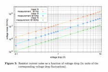
1. Resistor noise is proportional to the voltage drop across the resistor. The first two pictures are different because of different voltage. Note: That means that we may get the best use of "good" resistors by using them on high value resistors. For example, R7 and R13. The figure below is from the LIGO paper.
2. The last two resistors in the table match the lowest measured distortion at 0.0008%. They are Susumu RR which are the earlier SMD resistors and have higher noise and distortion than RG and the new RS according to Susumu.
3. In the LIGO paper, they agree that using a larger wattage resistor than is needed is helpful in getting low noise.
I think the Digi-key availability is very new. All of the Susumu RS at Digi-key are 0805 and all have 1000 in stock, just like they bought 1000 of selected values to see how they would sell and no one has bought any yet. At least they are willing to sell them in small quantity.
Jac
That is an interesting paper and different from what I had been looking at. Here is the link to the LIGO paper if anyone is interested.
https://dcc.ligo.org/public/0002/T0900200/001/current_noise.pdf
A few interesting things from the distortion paper.
1. Resistor noise is proportional to the voltage drop across the resistor. The first two pictures are different because of different voltage. Note: That means that we may get the best use of "good" resistors by using them on high value resistors. For example, R7 and R13. The figure below is from the LIGO paper.
2. The last two resistors in the table match the lowest measured distortion at 0.0008%. They are Susumu RR which are the earlier SMD resistors and have higher noise and distortion than RG and the new RS according to Susumu.
3. In the LIGO paper, they agree that using a larger wattage resistor than is needed is helpful in getting low noise.
I think the Digi-key availability is very new. All of the Susumu RS at Digi-key are 0805 and all have 1000 in stock, just like they bought 1000 of selected values to see how they would sell and no one has bought any yet. At least they are willing to sell them in small quantity.
Jac
Attachments
Last edited:
By the way Dario, I should have know that you would have already tried the RC55 and the MMA 🙂
Jac
Jac
melfs because of their "tubular" construction seem to have better power tolerance than the "flat plate" style typical of smd resistors.Would like to add, because it fits perfectly: had just seen this, very curious post of Patrick..
Would be really interesting to investigate deeper, what did he mean with this.. and which type of vishay/ beyschlag, the precision series or the standard MMB0207 or MMA0204?
http://www.diyaudio.com/forums/grou...measurement-amp-ikoflexer-29.html#post5123470
In addition the use of 4 in series parallel has increased the power capability by a factor of four AND reduces the voltage applied to each by 50%, while still maintaining the nominal resistance.
In my opinion, it would be even better to select a stack of series connected (lower value) resistors to reduce the applied voltage across each to much closer to the voltage applied to the lower leg of the NFB resistor.
Using 5 smd resistors in series instead of one high value one would be easy using a daughter board. Many PCB layouts allow a series stack of smds to be soldered into the trace.
The orientation of a helically wound component does not affect the inductance..................
I suppose he was referring to a topology to reduce inductance and lower noise (serial/parallel), probably two resistors with same orientation in parallel and then in series with another couple in opposite orientation.............
Two side by side (in series or in parallel) will perform exactly the same as two laid out similarly with one of the pair inverted. The orientation does not matter.
Now if manufacturers made available the same component with helical windings that could be CW, or CCW, then parallel or series combinations could use the CW+CCW to change the inductance.
As far as I know ordinary resistors cannot be ordered with opposite winding directions.
Last edited:
melfs because of their "tubular" construction seem to have better power tolerance than the "flat plate" style typical of smd resistors.
In addition the use of 4 in series parallel has increased the power capability by a factor of four AND reduces the voltage applied to each by 50%, while still maintaining the nominal resistance.
Yes, this is the mechanism and reason, l concur.
George
I think it would be better to pursue this than to guess engineer by swapping between different manufacturers.Yes, this is the mechanism and reason, l concur.
George
Lehmanhill, are you listening?
....I might compare some resistors......
Last edited:
I think it would be better to pursue this than to guess engineer by swapping between different manufacturers.
Lehmanhill, are you listening?
I am listening. That said, what I have been doing is researching low noise resistors by studying specs and noise measurements.
Once you get to suitable low noise resistors (metal or metal film) you will find that the dominant noise is Johnson and L/f.
You cannot much about reducing those any further.
Effectively all good low noise metal based resistors are as good as each other.
A 1k0 metal based resistor has a noise equivalent to ~4.1nV/root Hertz at room temperature. You get worse with badly made resistors, or metal oxide resistors, or very much worse with carbon resistors and don't even think about carbon comps.
Look at the NFB resistor string.
It is usually a ratio of 1:10 upto 1:30
The upper NFB resistor sees 10 to 30 times the voltage of the lower leg resistor.
That introduces a very small amount of distortion, due to resistance value changes (tempco) and due to voltage coefficient.
If you use one on the lower and ten in the upper for a 1: 10 ratio, you eliminate both of those effects.
Anything you can do to bring the upper leg resistor voltage drop down towards the lower leg resistor voltage drop improves towards elimination, i.e. the more resistors in series you can fit into the space on the PCB, the better the reduction of those two very small distortions.
Chosen badly those two distortions can be audible.
Chosen wisely those two very small distortions should be virtually inaudible.
Using the series ratio rule you can approach complete elimination of any measurable effect (way below audibility).
In my view you are wasting your time looking at any other swapping regime.
Hmm.. I'm not so sure that I'm with you anymore..
Your example, of the 1:10 resistors, for 1:11 gain by the way.. in a typical noninverting setup..
It brings 22 resistive-element <>circuit interfaces into the picture, in place of 4. And given that it had been always a big problem, it involves contact problems, dissimilar metal interfaces, thermal dilatation effects etc..
I think I would trust much more one, robust and well resolved solution in place instead.
Ciao, George
Once you get to suitable low noise resistors (metal or metal film) you will find that the dominant noise is Johnson and L/f.
You cannot much about reducing those any further.
Effectively all good low noise metal based resistors are as good as each other.
A 1k0 metal based resistor has a noise equivalent to ~4.1nV/root Hertz at room temperature. You get worse with badly made resistors, or metal oxide resistors, or very much worse with carbon resistors and don't even think about carbon comps.
Andrew,
If you haven't already, I recommend you read the study that I linked in post #3269. There you will find laboratory measurements that show that all metal film resistors are not the same for noise and that many are above the level of Johnson noise.
You are welcome to your opinion that I am wasting my time. The reality is that things like current noise, voltage coefficient, inductance, and capacitance are not "shared" with the public on datasheets in most cases. I am not alone in feeling that design, materials, and manufacturing processes make differences in those measurements. Since I can't measure those things accurately myself and because those measurements may not be a complete description of what is a good audio resistor, and mostly because I am curious, I choose to waste my time trying to understand design differences and swapping a few resistors to see if I can hear a difference.
Thanks for your interest.
Jac
Can you make out which resistor matches which curve?............
If you haven't already, I recommend you read the study that I linked in post #3269. There you will find laboratory measurements that show that all metal film resistors are not the same for noise and that many are above the level of Johnson noise..............
Can you extract all the known noisy types (carbon and oxide) and examine what's left, the metals?
Can you see a correlation within a power rating for all the metal types?
excluding 1/f, all the quieter ones seem to be very close to the Johnson noise from 1kHz upwards.
I'm afraid I can't make out all the colours, can you?
Last edited:
- Home
- Amplifiers
- Chip Amps
- My_Ref Fremen Edition - Build thread and tutorial