Hi Jaka Racman,
I am working on making up a circuit diagram with the LM361, U3, following the second LM6172, U2b. It sounds like very good advice to keep the gain on U2b low, probably less than 50. That way, U3 can get enough signal to function well, but U2b will not have to swing so much voltage that it is slowed down much. Then U3 will always keep only one 6N137 off at a time and thus only mosfet on at a time.
Hi Charles,
I like your precautionary advice about about keeping both 6N137's from being on at the same time. That should ensure that the circuit always oscillates. If you sent an email, the filter on the account must have blocked it.
There is a patent on a class D amp that is load independent. It uses a high Q output filter and a feedback circuit that takes care of the peaking filter response. Of course the feedback then needs to be taken from the output of the filter.
Try a search and you will find it. Could provide some useful info on the feeback in general.
/Marcus
Try a search and you will find it. Could provide some useful info on the feeback in general.
/Marcus
Hi Subwo1,
according to my simulations optimal gain for U2b would be somewhere between 10 and 20 (regarding dynamic range of signals), but I did not simulate with your values. At 50, bandwidth might be a bit to low (just a speculation, haven't tried it yet).
Regarding filter my expirience is as follows:
I have worked mainly with 100V ultra low Rdson fets (15mohm). My switching frequency was also higher, around 400kHz. In such configuration main problem are switching (due to large fet capacitance) and not conduction losses. Zero voltage switching aided by filter inductor ripple current cut idling current of amplifier by as much as 75%. That can easly be seen by change of idle current when one connects or disconnects filter inductor. Well, that would not work with your amp since it needs filter to oscillate, but as I remember Sergio also got lower idle current when he connected filter and adjusted dead time properly.
When thinking of filter components, polyproplyene capacitors are almost lossless. I have good experience with Wima FKP1 and Evox-Rifa PHE450 series of capacitors in resonant power supplies. They can carry 20 amps of resonant current at 280 kHz without serious heating. As far inductors are concerned, 10 times inductor really has 3.33 times many turns, but in my opinion much greater losses are due to proximity than to the skin efect. Proximity effect rises exponentially with number of winding layers, so air core inductor might not have the lowest losses although it is the most linear. Low loss inductor can be made by single layer winding on gaped ferrite toroid, but you need a diamond saw or file to make the gap on a standard ferrite toroid. Distributed gap cores (Magnetics MPP toroids) are not so linear with increased magnetization, and might not be a good choice, although they would stabilize switching frequency.
I look forward to your breadbording experiment. I have built some class D amplifiers (most based on triangle modulator) and simulated many more, but this one looks more promising than anything I have simulated before. Please post the results. I currently have no time to breadbord and debug the circuit, but I have a dream to do so in the future, especially to turn it into single supply full bridge circuit. I hate doing power supplies, especially symmetric ones.
Best regards, Jaka Racman
Hi marcus,
Thanks for the idea. We actually may not have thought to work on the concept without knowledge of the patents. So you are on the right track.
Hi Jaka Racman,
Thanks for more excellent advice. The gain of the opamp stage of 10 to 20 makes a lot of sense. I wish I also were'nt in a bind concerning the opportunity to build a prototype circuit 🙁
I think we have the gate charge/discharge problem licked with the IRF7343 source follower configuration. That should be one boost in performance, one of the main strengths of the N-champ concept. The other strength is the 6N137 which removes level shifting complications, with the only possible problem of some additional timing delay. But I don't see that as a problem, especially where high power is needed--subwoofer amps.
Your ideas on filters look very good. They seem perfectly valid, and I hope to implement them in the prototype. They fit well with my experience with switching power supplies which draw much less power when the transformer is connected.
I have not had probems with mylar capacitors, but it seems you have done better with polypropylene ones. I wonder if the cheaper mylar ones are OK to use. What you suggested with the ferrite torroid is exactly what I was considering doing as an alternative to large air cores, which I suspected might cause problems like circuit interference as well as losses. Those losses sound related to intrawinding capacitance. I may be able to use the circular saw with the diamond concrete cutting blade to make the cut.
Power supplies are a drudgery. I wonder if you considered the Universal SMPS as a possible alternate power source to standard 50hz transformer type. It is no more trouble to make a dual one as a single that way. Then, your amp may be simpler with no need to bridge. I guess you have seen that project at the link in my signature below.
I am very anxious to work on the circuit, but I fear I won't have the chance until next summer. Until then, I plan to refine the design and find alternative circuit configurations. Some may trade a little distortion for simplicity. For me, the simpler, generally the better.
Hi Jaka Racman,
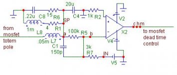
Besides comments on my last post, I thought I would also ask this related question. I have a bunch of NMB 20uF film capcitors. Do you think these have a low enough ESR to use along with a 50uH choke in the filter circuit? I did some simulations with those filter values, along with doubling the phase compenstion capacitor to 150pF, and fidelity improved dramatically. The improvements included better transient response without ringing and cleaner waveform output.
Besides comments on my last post, I thought I would also ask this related question. I have a bunch of NMB 20uF film capcitors. Do you think these have a low enough ESR to use along with a 50uH choke in the filter circuit? I did some simulations with those filter values, along with doubling the phase compenstion capacitor to 150pF, and fidelity improved dramatically. The improvements included better transient response without ringing and cleaner waveform output.
Attachments
total feedback
Well, yesterday I quickly tried to take the feedback signal from the very output. The results were these:
The gain was the expected, about 30 V/V (with a 33K and 1K feedback and input resistors).
However, I noticed that, at medium frequencies, the output was very distorted with a sine wave input.
Besides, at low frequency, there were high frequency oscillations superimposed to the signal.
What I think is this: perhaps the gain margin is very small. What if I put a capacitor in parallel with the feedback resistor so 1/2piRC gives my desired cutoff frequency, say, 30 KHz?
Any more suggestions?
Thanks!
Sergio,
Ahh, phase compensation? That is probably a good thing to try. The amp is losing control of the output is the way I would put it. Sometimes I just explain things funny since I just operate on an intuitive level. I never was any good with formulas and math.
Take Care
Ahh, phase compensation? That is probably a good thing to try. The amp is losing control of the output is the way I would put it. Sometimes I just explain things funny since I just operate on an intuitive level. I never was any good with formulas and math.
Take Care
perhaps the gain margin is very small.
It is the PHASE-marging actually that gets too low.
One possible solution would be the use of a double feedback loop as CREST does.
Another one would be the use of a controller topology called PID.
You can also make mixed feedback, i.e. feedback from before and after the output filter.
Taking feedback from the output filter would be much easier for a 2nd order LPF than a 4th order one.
In any case you have to add some circuitry to the LPF to make it stable for a broad range of load conditions.
Regards
Charles
Hi Subwo1,
I am not familiar with NMB brand capacitors, only NMB fans. Could you post a link to the datasheet ? In general I consider mylar inferior to polypropylene regarding ripple current capability, but since we are talking about RMS ripple current in the range 2-4A, 60mohm ESR would result in 1W loss. If your mylar is somewhere around this it may be useful. Polypropylene caps easily achieve ESR in the range 10 mohm or less. If you want really good polypropylene cap look for Sprague 735P 10uF 200V cap on this page. They are now sadly discontinued, but they are rated for 30A ripple current at 100kHz.
Regarding SMPS I have mixed feelings. It is hard for me to design yet another out of the mill power supply when I have to do much more exciting projects at my job (1MW regulated pulsed power in 2 shoebox volume). This does not imply that amplifier power supply is trivial or can be done with left hand. It takes almost the same effort and time, but it is just not so exciting. It does nothing per se, it only makes amplifier sing. If only could amplifiers work without power supplies.
Best regards, Jaka Racman
Hi Jaka Racman,
These NMB capacitors look like the ones my employer used in manufacturing over a decde ago. Maybe they were new old stock when I got them a few months ago, and for that reason I was able to purchase them for a good price.
I am getting some of the Sprague 735p's because they do look useful in future projects, if not needed in the N-champ project. Also, I was wondering if motor starting or running polypropylene capacitors are useful for much. I have several of those I obtained for a good price in the past.
I know what you mean about the drudgery of power supply designing. I have been designing, experimenting, and testing the Universal SMPS for a couple of years now. My Biggest Project So many things I want to make need lots of efficient power. I guess that was my motivation for expending so much effort on it. Your present 1 MW project makes my project seem almost trivial by comparison.
Best Wishes
If any one else wants to try building a class d amp, I am selling some Zetex parts in the trading forum.
http://www.diyvideo.com/forums/showthread.php?s=&threadid=19504
http://www.diyvideo.com/forums/showthread.php?s=&threadid=19504
Hi All,
Why so it is silent?
I have idea about voltage shifter from Crest/ssanmor (fig A) - it can be simpler and lower idle power consumption (fig B tested in real life)!
And MOST fast shifter- fig C.
Best regards.
Why so it is silent?
I have idea about voltage shifter from Crest/ssanmor (fig A) - it can be simpler and lower idle power consumption (fig B tested in real life)!
And MOST fast shifter- fig C.
Best regards.
An externally hosted image should be here but it was not working when we last tested it.
Hello, IVX.
Could you post the values of the resistors for the (b) figure? I am going to do some simulations.
Thanks!
Could you post the values of the resistors for the (b) figure? I am going to do some simulations.
Thanks!
Sorry, IVX, but i am not able to get the correct voltage values in the simulation. I am trying to simulate figure B.
Best regards
Best regards
I do not understand why...

An externally hosted image should be here but it was not working when we last tested it.
Hi IVX,
Good to hear from you again🙂 I do not like figure C because I don't think it will offer much immunity to transients that appear on the lower supply but not also on the top one. Kind of like what has been pointed out concerning the capacitor level shifting idea I had earlier. Maybe such ideas will work if the two voltage levels are actually coupled together with a capacitor. Then it would be like the opposite of decoupling. Then the noise signals may cancel out.
Figure B could be a little hard to turn off fully since the comparator has to get so close to the supply rail. Ahh, but that could be just what you are trying to do to speed up the transisor's response. So figure B looks pretty good as well as figure A, which is the same principle but with cascoding to get both current and voltage gain with fast response.
I also have a circuit which I would like to show. I will try to get it posted.
Simulated Alternative Method
OK, I have the diagram now. But, I would like to try using the 74C14 instead of the 5v 74HC14. Also, I would like to use 2SA1123 transistors for the differential input pair and current source instead of 2SA970 ones. I have experimented with this general method in actual circuits in the past, but not in a self-oscillating approach, and not with fast transistors. I had tried it with slow MPSA92 transistors in actual circuits with a 100khz oscillator, but the distortion was poor.
OK, I have the diagram now. But, I would like to try using the 74C14 instead of the 5v 74HC14. Also, I would like to use 2SA1123 transistors for the differential input pair and current source instead of 2SA970 ones. I have experimented with this general method in actual circuits in the past, but not in a self-oscillating approach, and not with fast transistors. I had tried it with slow MPSA92 transistors in actual circuits with a 100khz oscillator, but the distortion was poor.
Attachments
Hi subwo,
for fig C I expect good immunity (for this purpose BJT ` s give 30Vp-p, but for 4030 5Vp-p is enough) from 40v up to 60v able.
About handmake comparator-why to not buy cheap lm319 (319 it ` s much better than 393 - circuit in your figure is exact 393)
Taking a case I want to ask - what simulators you like. A question for all. About Micro-cap I heard good responses.
Best regards.
Simulators, Discrete Comparators, and Figure C
Hi IVX,
I like MicroCap because it is very fast to use. The schematics have a crisp, clean appearance. It does not require any programming skill.
I would think that an advantage of that circuit over other comparators, including the 393 is that it does not require much power supply consideration, and it draws very little power, like the LM393. Unlike the LM393, it operates off the main power supply rails. But I did not know about the existence of the LM393 though. I think one reason why this general approach did not work well for me in the past is that I was applying separate triangle waves to the input pins of the IR2113 and using both transistors in the differential pair to adjust the separate timing ramps on the IR2113 input pins. With this new circuit, the IR2113 is sure to get only opposite phased signals. Note: D6 should connect to the positive of the lower supply rail, not the negative.
Concerning figure C, I thought noise immunity in the level shifting was due to the high output impedance of the collector of the transistor. What advantage does the zener diode offer over capacitor coupling? Could the difference be the DC response of figure C? Is there any reason why the lower diode is not a simple switching diode? Best regards.
- Status
- Not open for further replies.
- Home
- Amplifiers
- Class D
- My very first Class D pwm (switching) amplifier.