
Done a functional test of Q7 & the 9vAC winding of my R-20A R-Core transformer.
Tested voltages:
Across 9vAC winding input = 9.37vAC
Across C7 (104 Ceramic) = 12.28vDC
Across GND & Output of LM317 measured at L1 = Currently set at 5.50v (to compensate for voltage drop)
So, I can guarantee that the Germanium Diodes won't blow with 1000uF of capacitance when 4x D7K's are arranged as a Bridge.
After reading Mr Loesch's work done on the Marantz CD-80 in this article:
Modifying A Marantz CD-80 CD \Player A blow by blow account of taking a venerable CD player and giving it a new lease of life. Article By Thorsten Loesch
And another look at the Schematic.
I'm convinced that a dedicated super-low noise possibly even shunt power supply feeding a 0.1ppm 11.2896MHz TCXO may do some good for it when used in a SAA7220 reclocking arrangement.
The current raindrop_hui schematic has the TCXO and the 74HC4040 being fed from the same power source as the notoriously noisy SAA7220! ... The SAA7220 has a current draw of 180mA, having such a huge current draw on a shared power supply bus, one that is shared with a TCXO and a binary counter chip is VERY BAD DESIGN!, But thankfully it may be rather easy to avoid this problem.
Seperation of these two power supplies will surely improve things. I want to be giving reclocking the best opportunity it can have.
Last edited:
Learnt some things last night.
#1, There is no need for such a high accuracy temperature-controlled clock such as a 0.1 ppm crystal.
#2, It is the 74HC4040 and the Crystal which does the reclocking and not the SAA7220. The SAA7220's sole purpose is to oversample the bitstream and remove the high end frequencies.
#3, The SAA7220 gives attenuation to the frequency response of the re-encoded audio bitstream as shown in Figure 4B
#4, Would be a good idea for me to print out some datasheets so I've always got them nearby.
http://www.analog.com/static/imported-files/application_notes/383160163AN207.pdf
http://lampizator.eu/lampizator/TRANSPORT/SAA7220.pdf
Let me know if these links are dead, I'll keep a copy of 383---.pdf on file.
Last edited:
Interesting. It says in the datasheet:
But on the PCB and in the schematic its connected to Analog ground on the TDA1541.
I say again this PCB seems like it was designed to deliberatley induce noise and malfunction in the circuit.
Pin no
13
mnemonic
TEST
description
Test Input: this input has an internal pull-down. In normal operation pin 13 should be open-circuit or connected to Vss.
But on the PCB and in the schematic its connected to Analog ground on the TDA1541.
I say again this PCB seems like it was designed to deliberatley induce noise and malfunction in the circuit.
Interesting. It says in the datasheet:
But on the PCB and in the schematic its connected to Analog ground on the TDA1541.
I say again this PCB seems like it was designed to deliberatley induce noise and malfunction in the circuit.
Why do that when Pin 12 is just 2cm away? Why go out of your way to send a single pin to analog ground wayyy over near to the TDA1541?
And incorrect it goes to Digital ground on the TDA1541.
EDIT:
Ahh, So it does connect to Vss (GND) on the SAA7220, Goodo!
Last edited:
Interesting.
Digital and Analog grounds join up together through C34 and R17.
Digital grounds for the CS8412, 74HC4040, SAA7220 & TDA1541 are all connected together and seperate from the Analog grounds, a good approach! But they rejoin through the components above.
Hopefully this will lend itself to being able to use an off-board dedicated power supply for the digital side without having to rejoin the two Analog & Digital grounds together.
Last edited:
Thats weird, On the schematic DGND of the CS8412 goes to Analog ground and not the common Digital ground.....Checking the PCB...
EDIT: Nope!, Phew, the CS8412 DGND goes to Digital Ground on the PCB, No need to alter it!
C31 of the SPDIF input goes to Digital ground (Good)
EDIT: Nope!, Phew, the CS8412 DGND goes to Digital Ground on the PCB, No need to alter it!
C31 of the SPDIF input goes to Digital ground (Good)
Last edited:
Error Flag, Pin 4, Is connected to the Common Digital Ground. I wonder if there is digital noise on the ground that this would dump whatever the SAA7220 is holding in memory and retry again.. Causing incredible jitter? Nope, this outputs an error signal whenever an error is detected by the SAA7220, it sends this data to the A Chip (SAA7210) (hence the name "error flag", imagine a little guy waving a flag.)
Might be a good idea to leave this pin floating so he can wave all day long and not be unencombered by being earthed.
Might be a good idea to leave this pin floating so he can wave all day long and not be unencombered by being earthed.
Last edited:
I'm not sure why people think this PCB is so bad? Its well designed.
Pin 14 (of SAA7220) is left floating, some cd player manufacturers don't even do this and let SPDIF data go to ground...
The only thing wrong with it that I've found so far is that the digital and analog grounds are connected together, but even so they are connected through a capacitor and a resistor. And Error Flag being put to ground. Which also really isn't so bad but isn't perfect, should be left floating.
And then there is the Positive rail of the SAA7220 going straight across the bank of decoupling capacitors for the TDA1541.. Sure okay, thats easy fixed with a jumper wire that pulls this rail further away from this chip.
The fact that it heavily uses Ceramic capacitors should be considered to be a good thing, this circuit /should/ be very silent RF wise, if it wasn't for the SAA7220 it would probably be quite quiet. It will be interesting to measure this RF noise with an Oscilloscope.
I find it strange that people think this is a bad design! Aside from the points above I can hardly see anything wrong with this.
I came into this project with the suggestion that this PCB is somehow faulty in many ways than one, and aside from distancing, and the use of OPAMPS (which some people like) and Oversampling (which again, some people like), and reclocking (ditto) and the use of LM317/337 3 pin volt regs, this board appears to cater to everyones tastes but doesn't do many things wrong...
If anything this board could be improved upon it would be that it has an I2S input added, and it used Shunt voltage regulators.
I will no doubt continue the search for something foul, but probably will not find something!
Last edited:
Hi Shane,
Yes this photograph was shoted few days ago after the fear of my life : I was in the middle of trafficjam on a motorway inside my Falcon-Millenium and just saw a HUGE tiger near WaltDysney France... and After saw a Roseta sattelite in Kanguru suit jumping from rocks to rocks... pills maybe ?!
I'm afraid with such hair Loreal cosmetics would not want of a model like me anymore 😀... have to launch my own brand for Wookies : LowReal Cosmos Ethic ?... natural wax for string and so on !
Freax, sorry for those little disgressions 🙂. you will find some usefull informations about the tda1541 grounding in some threads : of course ECDESIGNS ultimate TDA1541 one, also the pcb drawing RyanJ printed and called Distinction-1541... this is a quest, see the thread "Any good TDA1541 kit ?"... A lot of works will help you. And of course the oldest Jedi have maid it already : Audial online topics
Where were you on the night of September 1st 1975?
Attachments

Tomorrow is package day gents. Might see some action happen.
Meanwhile I stumbled upon this post, it describes an interesting approach of Biasing the opamps into Class-A.
http://www.diyaudio.com/forums/digital-line-level/190444-tda1541a-sound-signature.html#post2600069
Minor correction, its NOT Pins 1 & 4 its 6 & 4 according to this poster:
http://www.diyaudio.com/forums/digital-line-level/190444-tda1541a-sound-signature-2.html#post2602696
Where were you on the night of September 1st 1975?
yes this photograph was just before the first flight of Concorde, a beta version of Falcon Millenium.... pff above the ATlantic ocean I was fixing a Rolls Royce motor while Ian Solo was piloting to the George's garden !
I liked this musical period and interaction between the two side of the Ocean and the sea with Africa...
Sorry Freax for the off topic.
I am quite curious with your diodes, some say they prefer also germanium transistor with all their default : noise, temperature, etc ! They prefer it !
If you benchmark with Shotky diodes i will be pleased to read your opinion after the swaping experience : a good prof of concept in a particular case
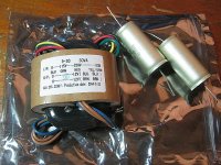
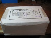
Two packages arrived. Pics attatched.
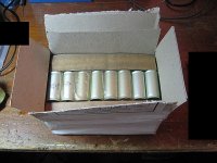
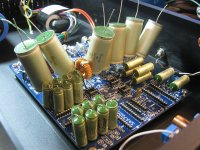
1x Big box of 22uF 63v PETP Capacitors 😀 (3x cardboard layers of capacitors this size, wow, gonna come in REAL HANDY.)
1x 115-230v R-Core 30VA 12v & 12v Transformer.
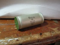
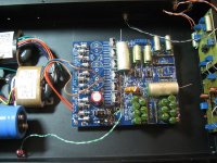
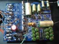
To give you an idea of how big these caps are I've attatched a photo of them sitting on the PCB.
Somehow I don't think mounting all of them vertically is going to work out too well 🙂
But with some velcro and some glue I'm sure we can mount them off the board...
1x Big box of 22uF 63v PETP Capacitors 😀 (3x cardboard layers of capacitors this size, wow, gonna come in REAL HANDY.)
1x 115-230v R-Core 30VA 12v & 12v Transformer.
To give you an idea of how big these caps are I've attatched a photo of them sitting on the PCB.
Somehow I don't think mounting all of them vertically is going to work out too well 🙂
But with some velcro and some glue I'm sure we can mount them off the board...
Attachments
-
 Picture 007s.jpg129.7 KB · Views: 160
 -
 Picture 005s.jpg75.1 KB · Views: 233
 -
 Picture 004s.jpg110.1 KB · Views: 225
 -
 Picture 002s.jpg92.5 KB · Views: 239
 -
 Picture 001s.jpg228.1 KB · Views: 255
 -
 Picture 008s.jpg275.1 KB · Views: 150
 -
 Picture 009s.jpg307 KB · Views: 213
 -
 Picture 010s.jpg116.3 KB · Views: 172
Last edited:
I couldn't resist trying out these 22uF caps in a coupling role...
Listening to Tina Turner - Goldeneye
The setup is:
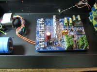
TDA1543 dac (Anarchist dac, previous project) with the Analog Metric PCB power supply (Q7) feeding the CS8412 and TDA1543 directly via BNC over RG6 Quad to the Scott17 KT88 SE Amp to Frugelhorns.
The left channel has the 22uF 63v PETP cap, the other channel has a 0.022uF PETP cap.
and I can really hear Tina Turner.... Including the sound room that she is singing in, I even feel like I can detail the microphone that she is using. You know how certian microphones have a certian charachter, well I can hear a bit of that.
Listening to Tina Turner - Goldeneye
The setup is:
TDA1543 dac (Anarchist dac, previous project) with the Analog Metric PCB power supply (Q7) feeding the CS8412 and TDA1543 directly via BNC over RG6 Quad to the Scott17 KT88 SE Amp to Frugelhorns.
The left channel has the 22uF 63v PETP cap, the other channel has a 0.022uF PETP cap.
and I can really hear Tina Turner.... Including the sound room that she is singing in, I even feel like I can detail the microphone that she is using. You know how certian microphones have a certian charachter, well I can hear a bit of that.
np: We don't need another Hero. (FLAC)
I can really hear the twangs of the strings on the guitar as the musician hits them, it sounds really nice. With the 22uF cap it makes them louder, more visible in the soundscape.
I can really hear the twangs of the strings on the guitar as the musician hits them, it sounds really nice. With the 22uF cap it makes them louder, more visible in the soundscape.
Last edited:
I'm confirming weather or not higher capacitance provides a positive benefit or a negative benefit to the music reproduction from my TDA1543 dac.
I unplug one channel and use only the right channel, I then compare each side of the DAC by switching the cable going to the amp between the two outputs. This should effectivley provide an accurate scientific comparison between the 0.022uF PETP cap and the 22uF PETP cap. Assuming one side of my dac IC doesn't sound different to the other side.
This removes the possibility of stereo imaging confusing my brain into thinking that one cap is superior to the other.
np: (FLAC)
Grimes - Genesis
Grimes - Oblivion
Grimes - Be a Body
Grimes - Symphoria
Grimes - Nightmusic
Grimes - Know the way
I play all songs through at least twice between switchovers between dac outputs.
Last edited:
22uF caps: (First impressions is that it sounds slightly louder)
np: (FLAC)
Grimes - Genesis (Noticed a difference at the beginning of the song, cant put it into words.)
Grimes - Oblivion (3/4 of the way through I noticed that Grimes's voice sounded more deeper, and bass felt deeper, also felt that the sources of the music were more seperated from each other and not prone to mix together in the soundstage.)
Grimes - Be a Body (The first Lyric "Be a body" feels more human and less synthetic, the synth at 0:41 and 1:04 feel more 8-bit like they come from a computer more instead of being muddled as before.)
Grimes - Symphoria (The chime sounds at the beginning sound more metallic than before, more like glass than plastic before, the snap at 0:54 has more snap to it....)
Grimes - Nightmusic (More bass, lots more, would describe it as fat sounding, violin instrument at the beginning sounds clearer. The synth starting at 1:45 feels more artificial than before. Bass is definatley more hard hitting than before, can't really tell much of a difference in the vocals.)
Grimes - Know the way (The water actually sounds like water now, almost (sounds like grimes used a low bitrate sample here), the string instruments (yes there are two there, ones a Sitar hiding in the background there.) feels more like a live string instrument, vocals sound unchanged from the 0.022uF caps and these ones.)
https://www.youtube.com/watch?v=igDsu5QWhpo
Very impressive, I might keep these caps in place.
Last edited:
- Status
- Not open for further replies.
- Home
- Source & Line
- Digital Line Level
- My version of the TDA1541 Analog Metric DAC