Yes I'm going to acquire 100% genuine LM317/LM337's over the next few years, only one LM317 which is on the Analog PSU circuit at the moment is 100% Genuine that I can vouch for, I'll add a picture of it to the end of this message.
Incorrect, the genuine LM317 (Q7) is feeding the SAA7220 directly and nothing else. It is feeding a Digital circuit. This is a good idea however I hate the fact that this trace goes directly next to the bank of decoupling capacitors on the TDA1541! not the greatest in noise isolation there...May have to bridge it with a wire and keep it away from the TDA1541 a bit more than is designed into the circuit.
Q6 (lm337) is feeding -15v on pin 15 on the TDA1541. (Analog)
Q5 (lm337) is feeding -5v on pin 26 on the TDA1541. (Analog)
Q4 (lm317) is feeding +5v on pin 27 & 28 on the TDA1541. (Analog)
Q3 (lm317) is feeding +5v on pin 8 & Pin 22 of the CS8412, this is a mix of Digital and Analog, bad design, its using Chokes to isolate each side.
Q2 (lm317) is feeding +18v for the opamps (all opamps are tied to this bus).
Q1 (lm337 is feeding -18v for the opamps (all opamps are tied to this bus).
And thats the schematic breakdown folks. not the greatest design especially when feeding the CS8412 analog and digital circuits, room for improvement there.
Last edited:
i hesitate also for the same output cap as yours as I have only two BG N for my TDA 1541 projects (One Distinction-1541 & two recent AYA 2 2014... you should go for it if Audial goes again whith such special low cost DIY operation). A good link for those caps ?
Maybe you mean these:
eBay item number:
250699037151
22uF K73-16 PETP's
Probably a good idea to match two of them to within 3% before using them too.
I guess there is no need to choose higher values. You might want to add some 47uF tantal or OS-CON capacitor near the chip, though..The main inductance value on the board/circuit is 47uH in the lm317 power supply circuit, I may use a higher value the through-holes on the pcb are large enough to support maybe 1-2mm of copper wire.
The (14x) 0.1uF is a minimum value, which performs well. Increasing it to higher values does however improve sonic qualities (I read). Even values well above 1uF seem to be acceptable for the TDA1541 and still improving SQ. Most easy is using foil-types. You could even use electrolytic (tantal) types there, but be aware of the polarity!Not sure if I will be using WIMA MKS2 caps, they are $5 each! Would be cheaper to simply buy the russian PETP equivalent. Getting them in the board however is a different matter.
Will be doing more research and taking this one step at a time.
eBay item number:
221113013675
Enter this into the search box of eBay.
Do a search on eBay for k73-15 or k73-16 or k73
Yes I have quite a few coils ready to be put into the circuit for ear-testing. I scavenge these ready-made from old blown ATX PSU's. But they are of a random mH value and I don't have a meter to check them.
eBay item number:
261546496952
These are nice however so might just buy them. The question is however what value to choose? I will need to learn some more about filtering the noise output of the LM317/337's.
I've got the premise of building this circuit around the notion that any RF present on the DC traces will invariably cause jitter.
So i've gotta isolate and compartmentalize... Which means more chokes and ferrite based chokes.
Something like this perhaps:
eBay item number:
351190288209
Schematic: TDA1541A DAC (CS8412/CS8414 + SAA7220) PCB - Analog Metric - DIY Audio Kit
The main inductance value on the board/circuit is 47uH in the lm317 power supply circuit, I may use a higher value the through-holes on the pcb are large enough to support maybe 1-2mm of copper wire.
Not sure if I will be using WIMA MKS2 caps, they are $5 each! Would be cheaper to simply buy the russian PETP equivalent. Getting them in the board however is a different matter.
Will be doing more research and taking this one step at a time.
Unfornatuly, those numbers are blocked in my Ebay browser because local restrictions laws... !
About the MKS2 : the 2.5 pitch cost more than the 5 mm but from my experience are different beasts. The 2.5 mm is much better.
try Farnell, Mouser, Digikey... believe it's less expensive here... Try values between 0.1 uF to 0.33... I should not go above on all the 14 DEM caps if just one value is choose (advised). But you can try also just the two or four first DEM caps with 1 to 2.2 uF (with the same Wima MKS2 2.5 mm pitch also and try a mix with your high inductance Z16 caps - because the pitch between legs- on the 10 following DEM position-) Notice some maid the opposite : big foil MKP foil cap on the two/four first DEM position and little pitc legs caps on the 10 DEM after... So the ears choose !
Should maybe use smd inductance on the trace like this fellow : First DIY DAC, Using TDA1541A ; maybe try 47 to 100 uH (smd is not expensive : just cut a trace, remove film on the traces, a little flux to solder the smt inductance et voilà !)
Should try old aluminium cap of 200 uF from the 80s (with bad high ESR) just after the LM regs for the analog section... to lower the Z (but use what you like near the oap you will choose 🙂 ) (i.e. : the aluminium caps keeped from your old player where you get the TDA1541 !)
Also as ESGIGT wrote : you can not be disapointed by old SANYO OSCON for the digital supply: I will try any value between 47 to 860 uF (pc mother boards) : 6.3 V for the two 6 V rails of the TDA 1541 and 16V for the -16V rail. I have some from a computer boards in 860 uF: fantastic ! the highers values are advised because very lower ESR : no problem to put 860 uf instead 47 uf, better in fact !
Also you should try polymers from UCC : ASA serie : cheap and very good, ihmo better than the Panasonic SEP/SEPC/SEPF !
Unfornatully have bought some Sanyo OSCON SP on EBAY (look at the Partsd section today for my testimonial ) but not sure they are genuine ! the SP "sounds" good also for their solid Cu legs !
But all those tips if able to improve the result can not fight against a bad layout and jittered chips like the old SA7xxx chips like the CS...12 spidf receiver. maybe have a look to Sure electronics on EBAY for their good Wolfson receiver at less 15 USD ! Worth it to benchmark against the Cirrus logic chip... but also the length of extra wires with two boards will add some jitter as well... so always the POC from the ears 🙂
cheers
Last edited:
I ordered 14x 10uF Elna Cerafine & 8x 100uF Elna Cerafine last night from the UK.
Also as stated earlier I've got 200x 0.1uF Glass ceramic caps arriving.
Also 24x 22uF Russian k73-16 PETP caps arriving.
Also have 47uH ferrite chokes arriving.
Also have the germanium diodes arriving.
Also have 0.47uF MKT Metallized Film Capacitor, x20
And a 12vAC/12vAC R-Core transformer arriving.
That just leaves the 3 pin Belden trimpots which i have an assortment of which should be close enough in value to work. and the resistors and 2x main filtering capacitors to select.
Last edited:
Unfornatuly, those numbers are blocked in my Ebay browser because local restrictions laws... !
I'll paste the descriptions of them so you can search for yourself, you may need to search worldwide however. Or I'll paste the direct links.
1x 30W 115V/230V R-Core Transformer 18V+18V,9V+9V+9V
1x 115V/230V 30W high quality Audio R-Core Transformer 12V+12V
20x D7J/ Д7Ж/ USSR GERMANIUM ALLOY RECTIFIER DIODE 400V 300mA FOR AUDIO
50x 47UH 900mA 6x8mm Power Plug-in Inducers Magnetic Core Inductors
100x Miniature De-Coupling Capacitors 0.1uF= 104= 100nF 50v Ex Mil Axial Ceramic
24x Russian K73-16 PETP Capacitor 22uF 10% 63V ,
20x 0.47uF 470nF 63V MKT Metallized Film Capacitor
This sounds interesting thanks for the tip.Should try old aluminium cap of 200 uF from the 80s (with bad high ESR) just after the LM regs for the analog section... to lower the Z (but use what you like near the oap you will choose 🙂 ) (i.e. : the aluminium caps keeped from your old player where you get the TDA1541 !)
The intial plan was to go with Elna Cerafines but I'll try other brands no problem. The main reason why I've got Panasonics in there is because I cannot find any Elna Cerafines in that value (4700uF). Infact I do not have any capacitors in that size at the moment.Also as ESGIGT wrote : you can not be disapointed by old SANYO OSCON for the digital supply: I will try any value between 47 to 860 uF (pc mother boards) : 6.3 V for the two 6 V rails of the TDA 1541 and 16V for the -16V rail. I have some from a computer boards in 860 uF: fantastic ! the highers values are advised because very lower ESR : no problem to put 860 uf instead 47 uf, better in fact !
UCC ASA ok. Those will have to wait to be ordered until the next order from the UK.Also you should try polymers from UCC : ASA serie : cheap and very good, ihmo better than the Panasonic SEP/SEPC/SEPF !
Last edited:
If you're wondering what a DV709 is, its a transformer...Completely unnecessary in the circuit so just bridge the wires to the CS8412.
Last edited:
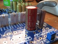
Decided to pull the 6800uF Panasonic caps out and replace them with whatever Elna Cerafines I have left, I only have 2x 1000uF 35v Cerafines so i'll use those where they can do the most good, in the TDA1541 power supply section (Pos Bus Q7/Q3/Q4 & on Neg Bus Q5/Q6 on Windings 12vAC & 15vAC) May not be enough capacitance and I'm aware of that issue. will measure voltages once running. I've read that LM317's/78xx's prefer a bit of ripple anyway/work better.
Last edited:
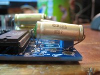
Pics of things done today.
One thing that I want to mention, this board is pretty much completely reversible back to its new condition, the PCB is SO THICK that you can solder suck the capacitors out, use some Goot Wick to remove the rest of the solder, heat up the pad and then use a tissue to wipe down the board and the area around the pad and the pad itself will be returned back to its original starting point, if you like cosmetics and like to keep your PCB boards clean and like to be able to clean them up after you've done a good job and make them look good then this is the PCB board for you!
Installed some resistors.
For some reason can only seem to find one Elna Cerafine, I thought I had two of them, I must've lost one of them somewhere. 😱 Anyway I put the one that I could find into the circuit. Will have to source 3 more of them which I'm not happy about. I'm sure the other one is around somewhere.
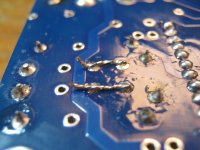
I added jumpers to replace the DV transformer.
I also added 2x 0.022uF K73-15 caps to couple the SP/DIF input into the CS8412.
One thing that I want to mention, this board is pretty much completely reversible back to its new condition, the PCB is SO THICK that you can solder suck the capacitors out, use some Goot Wick to remove the rest of the solder, heat up the pad and then use a tissue to wipe down the board and the area around the pad and the pad itself will be returned back to its original starting point, if you like cosmetics and like to keep your PCB boards clean and like to be able to clean them up after you've done a good job and make them look good then this is the PCB board for you!
Installed some resistors.
For some reason can only seem to find one Elna Cerafine, I thought I had two of them, I must've lost one of them somewhere. 😱 Anyway I put the one that I could find into the circuit. Will have to source 3 more of them which I'm not happy about. I'm sure the other one is around somewhere.
I added jumpers to replace the DV transformer.
I also added 2x 0.022uF K73-15 caps to couple the SP/DIF input into the CS8412.
Attachments


Last edited:
I guess there is no need to choose higher values. You might want to add some 47uF tantal or OS-CON capacitor near the chip, though..
The (14x) 0.1uF is a minimum value, which performs well. Increasing it to higher values does however improve sonic qualities (I read). Even values well above 1uF seem to be acceptable for the TDA1541 and still improving SQ. Most easy is using foil-types. You could even use electrolytic (tantal) types there, but be aware of the polarity!
yes I read this too from here:
SATCH-DAC
I have already agreed to use 0.470uF MKT Films.
However I have 0.022uF K73-15's in there as decoupling caps at the moment, we can start from there and move onto the MKT 0.470uF Films. Then move onto Polyester or Paper in oil.
I also want to buy some 0.47uF K73-16 capacitors to try the PETP caps out in a higher capacitance value for decoupling caps but they are proving to be difficult to find.
Then after that I can swap out the 100uF Elna Cerafines for Black Gate 100uF caps.
Will also be trying out the 22uF Russian k73-16 PETP caps for coupling purposes. (I'm expecting them to be epic).
I'm also eyeing off these for coupling capacitor purposes:
http://www.hificollective.co.uk/cat...-jensen-metallised-polypropylene-p-10091.html
Last edited:
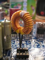
Put a massive high current Differential Choke on L2 (Q6 -15v Bus for TDA1541)
Ohms reading on each solder tab is 000.4 Ohms, I don't know anything else aside from the fact that it came from an ATX PSU.
Using this calculator:
Toroid Winding Calculator ? 66pacific.com
I've figured out that its 27 turns and is approx 2.6uH using a Yellow T-30 Size Iron powder core.
I do have another ferrite core which is much thicker but about the same diameter, may need to get some new copper wire online and wind my own high inductance core.Turns required: 27
INDUCTANCE
Desired: 2.6 uH
Calculated: 2.6 uH (101% of desired)
CORE
Part number:
Freq. Range: 3 to 50 MHz
u: T-30-6 (Yellow)
AL: 8
36 uH/100 turns
Last edited:

May need to get myself some Tantalums:
SATCH-DAC
SATCH-DAC
Looking at the parts, power supplies, caps, filters etc. - this player does not need any upgrading except if you wanna go full black gate which is another story entirely. My own trick is not to spend $$$ for B-G caps but instead I bypass the stock electrolytes in power supplies of the TDA1541 and CS receiver with 47 uF/16V tantalums. the result is similar to B-G job.
After a week the DAC shows very strong performance, and improved marginally from the first test. The Nichicon Muse capacitors which it is full of, are good, but nothing to write home about. I feel that Oscons and Blackgates or Elna Cerafines are better.
I also added 2x 0.022uF K73-15 caps to couple the SP/DIF input into the CS8412.
hI, 😱
The best way to avoid noise from PS with digital chips is to put the littliest cap size you can because the inductance and the nearest from the pins. : smt caps, or 2.5 pitch legs bulk caps...
You may put some of your very huge caps for the local PS decoupling as energy reservoir "to tailor the sound color" but with the very low values used around the CS8412 with such big case, I doubt it could be better🙄
Try both method and tell us....
I don't really understand where you will put all those caps you are buying ? Are you talking only on the digital stage and the final analog output DC cap... Well tryed mysel the K-76... on a raindrophui AD1865... few improvement to wait from such tweaks... a little improvement yes, but not so great. You may have better improvement with a tweak on the PS, I/V stage, input digital stage (swap the CS8012... instead buying the same price in caps...ihmo, had a similar try some years ago with such chineese ebay kits !)
cheers
Last edited:
hI, 😱
The best way to avoid noise from PS with digital chips is to put the littliest cap size you can because the inductance and the nearest from the pins. : smt caps, or 2.5 pitch legs bulk caps...
You may put some of your very huge caps for the local PS decoupling as energy reservoir "to tailor the sound color" but with the very low values used around the CS8412 with such big case, I doubt it could be better🙄
Try both method and tell us....
I don't really understand where you will put all those caps you are buying ? Are you talking only on the digital stage and the final analog output DC cap... Well tryed mysel the K-76... on a raindrophui AD1865... few improvement to wait from such tweaks... a little improvement yes, but not so great. You may have better improvement with a tweak on the PS, I/V stage, input digital stage (swap the CS8012... instead buying the same price in caps...ihmo, had a similar try some years ago with such chineese ebay kits !)
cheers
Hi,
Those two 0.022uF caps are in the place for C32 and C34.
As for using caps on the pins of CS8412 I agree completely but I won't go as far as using SMD but instead glue discrete capacitors to the PCB and then bend the leads to the chip pins.
I really want to go overkill on this design with the most amount of filtering possible, all kinds of filtering.
"All those caps that I am buying" are going into this kit aswell as other projects, I always buy in bulk. I can also always re-use caps in amplifiers & future projects.
I also didn't buy the chinese DAC kit, instead I bought the PCB so I need all of those electrolytic capacitors.
Last edited:
You should buy for few money the Subbu V3 (few bare pcbs with the dac chip are sold yet in the GB section). Follow the genuine BOM and if you want the "Subbu Modyfing thread" and do a listening benchmark with the huge Ebay kit you have !
Very instructive: a good layout with a low cost dac chip can sound good ! I learned from this than the dac chips and caps are not enough but the layout also have a great place if not the most important !
Here you have a great dac chip with your gebnuine TDA1541 but ihmo wasted by the layout of this ebay pcb ! But yes finish it and rapidly go for a AYA 2 2014 if you have the luck to have a second edition curse or such low cost Subbu DIY kit... You will not regret it ! 🙂
But defintly yes, tweaking is a great way to improve, learn and tailor a kit in relation to the rest of your hifi system 🙂
Good luck
This PCB is going to be going through a lot of changes don't worry about it.
This PCB contains everything to get started on the one PCB, ontop of that its cheap as chips, a great place to start for heavy modification.
I already done the cheap and cheerful thing with my Anarchist TDA1543 DAC. It sounds great but not as great as my TDA1541 used to sound like, right now its making no sound at all, so here I am.
http://www.diyaudio.com/forums/digi...chist-dac-pcb-layout-suggestions-welcome.html
Last edited:
- Status
- Not open for further replies.
- Home
- Source & Line
- Digital Line Level
- My version of the TDA1541 Analog Metric DAC