Summary Post
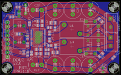
Just to bring a bit of closure to this little project: the main point was to introduce myself to board design. And in that regards these are a huge success. At the end of the day, this design is really just a tweak of DUG's design. The schematic is identical to DUG's, except for the addition of two power supply decoupling capacitors. All the component values use the same identifier (i.e. R1 on this board has the same function as R1 on DUG's board).
Because this is literally a first design from a novice; and also because DUG and GMARSH have excellent group buy boards available, I assumed no one would be interested in these boards. And indeed, so far jfetter is the only one who's shown interest in actually getting these boards.
But in the spirit of being an "open source" project, here I'm posting a few things for anyone who might be interested in this project:
Thanks again to everyone who helped me with this design!
Just to bring a bit of closure to this little project: the main point was to introduce myself to board design. And in that regards these are a huge success. At the end of the day, this design is really just a tweak of DUG's design. The schematic is identical to DUG's, except for the addition of two power supply decoupling capacitors. All the component values use the same identifier (i.e. R1 on this board has the same function as R1 on DUG's board).
Because this is literally a first design from a novice; and also because DUG and GMARSH have excellent group buy boards available, I assumed no one would be interested in these boards. And indeed, so far jfetter is the only one who's shown interest in actually getting these boards.
But in the spirit of being an "open source" project, here I'm posting a few things for anyone who might be interested in this project:
- BOM, in three formats: CSV, PDF, and ODS. Content is the same in each file, I'm providing three formats for convenience.
- Eagle files: the SCM and BRD (schematic and board) files.
- Gerber files: in case you want to have them fabricated. I had the fab done by Elecrow without any issue (under $20 shipped to USA for 10 boards!)
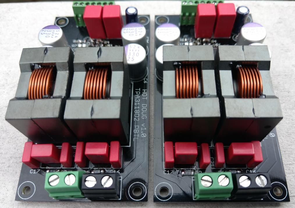
- And some pics of two finished boards
Thanks again to everyone who helped me with this design!
Attachments
-
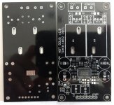 bare_board_back_20160810.jpg82.3 KB · Views: 392
 -
 bare_board_front_20160810.jpg91.4 KB · Views: 394
 -
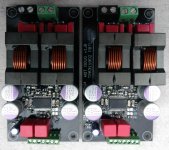 stuffed_pair_1_20160820.jpg84 KB · Views: 403
 -
 stuffed_pair_2_20160820.jpg92.3 KB · Views: 612
 -
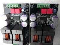 stuffed_pair_3_20160820.jpg112.6 KB · Views: 395
 -
tpa3118_pbtl_bom-20160826.zip74.9 KB · Views: 122
-
tpa3118_pbtl_eagle-20160721.zip113.5 KB · Views: 125
-
tpa3118_pbtl_gerber-20160721.zip134.2 KB · Views: 97
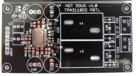
While I love the deliciously overkill Coilcraft VER inductors, they consume a significant amount of board real estate (and are expensive and only available directly from CC). So I tweaked the design a bit, here's version 2.0. Changes:
Too many projects in the queue right now to actually fab and experiment with these. But if anyone is interested, let me know and I'll provide any desired files.
- Use ICE Components 1D14A inductors instead of Coilcraft. Cheaper, smaller, easier to get, but still with decent specs.
- More power supply decoupling capacitors. Save money on Coilcraft inductors and spend it on OS-CON capacitors. 😉
- Overall reduced board size, 70x44
- Added an on-board LED
- Added a header pin for an off-board LED
- Actually labeled the header pins/terminal blocks
Too many projects in the queue right now to actually fab and experiment with these. But if anyone is interested, let me know and I'll provide any desired files.
Attachments
Very nice - looks like brute of a TPA 😀
I personally, think the CC's are the main badge of honor on these amps so would keep them.
These look really awesome, excellent work! But, Matt, we gotta know...how do they sound???
Well, to be honest, I haven't done any critical listening with them. 😱 My main goal was to familiarize myself with PCB design and actually produce something that works. And in that regard---thanks to much hand-holding from this community---it was a great success. (Also, thanks to Gmarsh's tips, I now having experience doing reflow soldering via frying pan!)
That said, at least with casual listening, I don't hear any obvious flaws. In fact, I'm a little scared to attempt any true critical listening with these, for fear of extreme "baby bias" (they are my babies, after all).
Also, basically as soon as I validated that they were working, I shifted gears to focus on DACs. Some day I'll circle back to amps. 🙂
Ha, fair enough. Well you definitely did a great job, and it's always fun to pick up a new skill. Do you have a BOM? I might be interested in building one if the cost isn't too great.
Sent from my XT1096 using Tapatalk
Sent from my XT1096 using Tapatalk
Ha, fair enough. Well you definitely did a great job, and it's always fun to pick up a new skill. Do you have a BOM? I might be interested in building one if the cost isn't too great.
Yup, the BOM is posted above in post #61.
If you're pretty serious about doing this, I have some extra un-populated boards I could send you, assuming you are in the USA. PM me if interested.
The BOM isn't exactly cheap, particularly because of the Coilcraft inductors, the fancy film caps, and the OSCON capacitors. Of course you can substitute accordingly, as long as things will fit.
Note some people have been able to obtain free sample inductors from Coilcraft. The price of their actual inductors isn't too bad in my opinion, but with their manufacturer-direct model I don't think they are targeting small quantity hobbyists like us. So they don't have any super low-cost shipping methods, which means for small orders, the effective per-inductor price becomes rather high once shipping is factored in.
By the way, all the above applies to the v1.0 board. The v2.0 board that I recently posted I haven't actually had manufactured, nor have I created a BOM for it (although the bulk of it is the same as v1.0, just a few tweaks).
matt, i'm thinking the CC inductors possibly have a minimum distance requirement to cancel open solenoid interaction?
silly question but would the amps sound change if the CCs are bucking or in phase relative to physical mounting?
bruce
silly question but would the amps sound change if the CCs are bucking or in phase relative to physical mounting?
bruce
The gaps for a magnetic field to be generated are generally in the centre post.
How much of that magnetic field gets out would be one question.
How much of that field is picked up by and affected by the nearest coil would be the other.
Interesting to think about.
Electric field would be produced by windings/traces/IC pins.
Probably radiated but not picked up due to impedance mismatch between field and receptor.
One could do a channel separation test to see if that is affected.
The gaps for a magnetic field to be generated are generally in the centre post.
How much of that magnetic field gets out would be one question.
How much of that field is picked up by and affected by the nearest coil would be the other.
...
At the risk of embarrassing myself with a possibly spectacular display of ignorance... in PBTL, isn't one output "pushing" the signal and the other "pulling" the signal? And if so wouldn't that mean that any generated fields would be in opposite directions? If they were moving towards each other, might they basically cancel each other out?
I was thinking about making another revision of this board that completely eliminates the output LCR filter. The tpa311x datasheets say these amps can be used with only a ferrite bead if the speaker cable length is short enough. That would save board space and BOM cost. And it might improve sound quality, if the filter is indeed imparting any kind of sound on the signal. I was also thinking of stealing the onboard capacitor multiplier idea from the Volt+ or Folsom's tda7297 amp. So imagine tpa3118 monoblocks, designed to be placed really close to the speakers (maybe even integrated into the speaker), with the power supply (semi-)integrated into the board.
Also, wouldn't removing the LCR filter eliminate the speaker impedance matching problem of these (and most other class-D) amps?
Thoughts?
Last edited:
Yes in one case its buck and other boost. There are four possible arangments.
boost-boost
boost- buck
buck- boost
buck- buck
It would be interesting to do a series of tests.
No do not even think about filterless.
Incredable EMI , like hundreds of broadcast stations splattering rf.
Even with beads.
The other case on the ferrite solenoid is saturation with lowz load.
Two things Im exploring - air core torroid and off the shelf torroids.
In my past life I did in-house CE markings & assessments.
-bruce
A FB filter is perfectly adequate as long as you keep the output wires short. So it's well suited for powered speakers as you mention
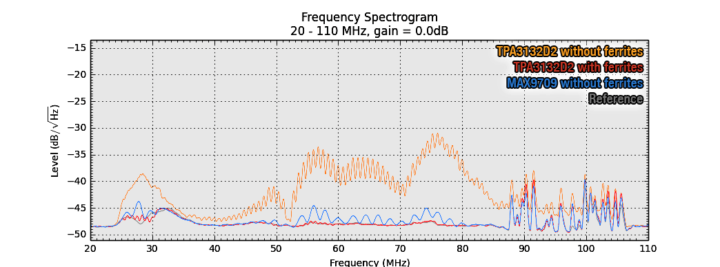
+1, I use TPA3132D2 with FB-filter and MAX9709 completely filterless, no problems.
And i measured them both.
TPA3132D2 vs. MAX9709 Messungen EMI/EMV ? #360customs
And i measured them both.
TPA3132D2 vs. MAX9709 Messungen EMI/EMV ? #360customs
+1, I use TPA3132D2 with FB-filter and MAX9709 completely filterless, no problems.
And i measured them both.
TPA3132D2 vs. MAX9709 Messungen EMI/EMV ? #360customs
Conducted emissions ?
looks like only radiated?
Are those worst case plots 0-360 rotation?
a known emi source and is bad engineering to use filterless.
It's not bad engineering, it's just a compromise. An LC filter is indeed better EMI wise, but a FB filter is waayy cheaper and smaller. With short output leads it's a good compromise, in some other applications maybe not so much.
It's not bad engineering, it's just a compromise. An LC filter is indeed better EMI wise, but a FB filter is waayy cheaper and smaller. With short output leads it's a good compromise, in some other applications maybe not so much.
If its not released for volume production, sure no problem.
If its re-called or requires post production EMI revisions, then its a blank check $$$.
The plots are made with the antenna in parallel with the speakers leads. (1.5m leads untwisted unshielded, 0.7m antenna, distance between then 0.5m) So yeah, pretty much worst case. These boards are intended to be used within active speakers. The ferrites dampen it quite good. It can also be seen that THT ferrites perform worse due to their leads.
Last edited:
- Status
- Not open for further replies.
- Home
- Amplifiers
- Class D
- My tpa3118 board - comments/critiques?