chipco3434 said:
I understand the switch to 1/2 watt in positions r5 (and R6?) but don't understand "and added a second 221 Ohm 1/2w".
For use with the PE tranny, I am placing (2) 33V 1w zeners in ZD+1 and ZD+2 with jumps at ZD+3 and ZD+4. On the - side, one 15V 1w at ZD-1 and jumps on ZD-2, ZD-3, and ZD-4. If this is not correct, would somebody let me know before the smoke gets out.
Thanks!
Sounds right to me. 🙂
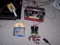
So, I got tired of waiting for my case to come (par metal) and decided to rig the XBOSOZ on the floor and try it out. I connected it single ended in and out from and old (but good) SACD player to a pair MyREF Rev. Cs monoblocs. I used my "twisted log" relay attenuator with 2.2K output impedance and input impeance from about 4K to 28K, and easy enough load for the XBOSOZ.
I tried the attenuator on input, and quickly found it not to my liking, way too much hiss, so I put it on output. WOW!!! dead quite now, what a difference.
As for sound, well I could not turn it off all day yesterday and today. 🙂 It is in fact still on. Very muscal and lush bass, awesome clear details, absolutely rock bottom noise floor, noise is undetectable to my ears unless I put my ear to the tweeter.
Thanks to all who got the project to where it is. I am very pleased with the result so far, much more than I actually expected.
Cheers!
Russ
Member
Joined 2002
Re: Here is the ugly pic 🙂
Can we perchase them transformers off of you ?
Russ White said:Looks aweful, sounds wonderful 🙂
Can we perchase them transformers off of you ?
Tested my power supplies this morning and seems like something's a little off. I have -14 and +72 on the outputs. The bad part is that the zeners on the + side get pretty hot after just a few seconds. I doubt if they would last a minute.
I am using (2) 33V 1w zeners in ZD+1 and ZD+2 with jumps at ZD+3 and ZD+4.
Is there a resistor change I can make to get that voltage down a little?
Should I bump the wattage rating of the zeners?
Can I parallel 2 more 33's?
Can I change a resistor to lessen the current flow?
Some many questions... so little knowledge.
I have no idea why your zners are getting hot, that is strange. My zeners don't even get warm. :😕
Are you using kit parts except for the zeners?
Are you using IRF610 and IRF9610 for the PS FETS?
Just want to be sure I understand the situation.
Are you using kit parts except for the zeners?
Are you using IRF610 and IRF9610 for the PS FETS?
Just want to be sure I understand the situation.
Some questions for the experts
1) C1 on my preamp seems to get pretty warm. Looking at the traces I don't think it is too likely that the heat is being conducted from R1/R6,R2/R7 instead I wonder if the heat is being generated by D1 (6.3V zener for the CCS). this made me wonder if 6.3V is the optimal value for any negative rail voltage, or if it should be adjusted. In any case I will try it with that diode elevated above the cap and see if it helps.
2) Does C1 need to be bipolar? The schematic I started from had it as bipolar electrolytic, but I wonder if 105C 22uf standrad electrolytic would serve just as well. If a standard electrolytic will work I assume the positive lead should go to GND. Is that correct?

What voltages are you using on your power supply?
There seems to be a difference from Karis boards.
There seems to be a difference from Karis boards.
promitheus said:What voltages are you using on your power supply?
There seems to be a difference from Karis boards.
Who are you asking?
If you are asking me. I am using metalman's PS circuit, not Kari's, and the voltages are the same as what metalman did.
http://www.diyaudio.com/forums/showthread.php?postid=763865#post763865
which is +70V and -20V
oops, yes of course who was I asking? 
Sorry about that.
I was asking Russ White.
Why do use higher negative voltage?
Is there a reason for that?
Sorry about that.
I was asking Russ White.
Why do use higher negative voltage?
Is there a reason for that?
metalman said:C1 does NOT need to be bipolar, and the +ve terminal goes to ground.
Ok then here is a very important building note for my PCB. For some reason (I think I drew something in a wrong layer) the C1 cap is shown with only one solid white line (it should have two denoting bipolar). The positive side is where the white line is, that is OPPOSITE of the way caps are usually marked. So if you don't use a bipolar cap (such as the one supplied with the TP kit) make sure you get the polarity right.
Are you using kit parts except for the zeners?
Yes
Yes, and remarkably, they are in the correct position.Are you using IRF610 and IRF9610 for the PS FETS?
More news...
Each board works fine on its own with the correct voltage. When both are powered by the tranny, that's when things go funky.
Diodes warm up to hot. When each board is powered independantly, diodes do not warm. Should I tie my AC ground to board ground -0-DC?
The 55VAC and 16VAC on the PE tranny are both center tap.
I am off to the Milwaukee Symphony. Feel free to discuss in my absence!
Thanks, and I'll see you at 6PM!
The 55VAC and 16VAC on the PE tranny are both center tap.
Is it possible that they (both the 55v and 16v) are actually the same winding, ... do they share the same center tap? I hope not 'cause then it's not gonna work
 I think they need to be totally isolated for this application....and if they have the same ct I don't think they are isolated.
BTW: I speak from hard experience, I blew all my diodes making that particular mistake but rereading your post you may have a different problem...

eapavant said:The center taps are isolated. I have the pe transformer working.
Oh that's good. As usual I'm a 'doomist'

Yes, the center taps are isolated...
I think that I have an IRF9610 pooched on one of the boards.
The good board reads -14.6. The bad one reads -11.2 volts.
When I check across the pins on the 9610 I get
-14.6 / -20.2 / -14.6 on the good one and
-14.6 / -20.2 / -11.2 on the other.
Any insights?
(MSO was pretty good tonight! I like to compare the sound in the den to the sound in the concert hall)
Thanks guys!
- Home
- Amplifiers
- Pass Labs
- My Take on X-BOSOZ