Salas,
I am not joking about prefiltering with SuperTeddyReg,
Probably prefeltering as you said, is the correct term. To say preregulating would be rather optimistic as a term. Just because I don't see where is the reg part in that cct in the link. I see a voltage reference and gyration. But then again I am not an engineer and maybe I miss something.
ikoflexer said:In my opinion, if you really want to improve the psrr by a lot, use a cap multiplier or a gyrator in front of the regulator. The increase in line regulation will be a lot more than what is obtained from tweaking the mini-CCS.
@Ikoflexer
yes, basicaly, STR is a gyrator + voltage reference, as Salas wrote 🙂
ikoflexer said:Still, if the load circuit should have very critical filtering, adding one or even two cap multiplier/gyrator circuits before the regulator will do much more. For a phono stage for instance, it should be definitely considered. The only issue is that you must have enough voltage at the input, because each of these circuits needs some voltage drop to operate.
More detailed, STR is two gyrators with LPF filter + additional accelerator circuit (to faster charge C3 through Q5)
You wrote to prefilter shunt reg with gyrator or two of them and I replied that good job on gyrators is already done.
Circuit can be tweaked, pass transistors can be replaced with MOSFETs, but this is personal preference.
TeddyReg high end voltage regulator
This is TeddyReg, much easier to understand.
Gate of Q1 is biased through 2nd order LPF, Q1 is used to bias pass transistor Q2.
Not real regulator, just gyrator.
This is TeddyReg, much easier to understand.
Gate of Q1 is biased through 2nd order LPF, Q1 is used to bias pass transistor Q2.
Not real regulator, just gyrator.
Last edited:
That is the original Teddy yes? That has a reg stage indeed. LM317.
Which one people tend to like the most?
Which one people tend to like the most?
Yes, 317 is regulating. But if you delete everything before R3 and R4, then only gyrator is left 🙂
I never built this version with LM317, but others reported that SuperTeddyReg is marginally better than LM317 version.
A lot od them also reported that gyrator with MOSFET is better, but Teddy decided that MOSFET gyrator have "to much bass" and D44H11 should be used 🙂
Here is "grandpa" 🙂
LINK
I never built this version with LM317, but others reported that SuperTeddyReg is marginally better than LM317 version.
A lot od them also reported that gyrator with MOSFET is better, but Teddy decided that MOSFET gyrator have "to much bass" and D44H11 should be used 🙂
Here is "grandpa" 🙂
LINK
Last edited:
You never know from system to system. They probably are all rightfully speaking with each one's speaker and room.
Good stuff!
A word of warning. I'm saying this for the benefit of those that wonder through these woods and get to read these accounts. There are circuits which have an inherent high output impedance. Most (if not all) cap multiplier, gyrator, pre-filter type circuits fall in this category. If they get connected directly to a load that does not draw current at a steady rate, what you get is a variable voltage at the input of the load. How variable? Depends on how much the load current varies. Imagine a headphone amplifier and some slow music followed by a cascade of power drums, base, and other stuff, Beethoven's 5-th is a good example of very mellow music at times, followed by some huge dynamics at times. When that happens, the big dynamics draw current all of a sudden, which is definitely a constant 300mA. Jumps all over like a crazy bunny from 5mA to 500mA maybe, at different frequencies one on top of another. The amp draws this current, but if the power supply behaves like a resistor (has high output impedance), a voltage variation that is proportional to the current drawn is modulated on the input of the amplifier. In such moments your amplifier gets a voltage input that jumps all over the place, maybe by even 0.25 volts. I'm just pulling these numbers out of the hat to exemplify the effect. It could be worse, depending of the circuit. Now you see, why we're trying so hard to build a regulator which has very low output impedance even at frequencies past audio. When the amp draws current, the regulator gives it without a problem while keep the voltage as steady as possible. The faster the regulator can respond to the demands of the load, the better it is.
A word of warning. I'm saying this for the benefit of those that wonder through these woods and get to read these accounts. There are circuits which have an inherent high output impedance. Most (if not all) cap multiplier, gyrator, pre-filter type circuits fall in this category. If they get connected directly to a load that does not draw current at a steady rate, what you get is a variable voltage at the input of the load. How variable? Depends on how much the load current varies. Imagine a headphone amplifier and some slow music followed by a cascade of power drums, base, and other stuff, Beethoven's 5-th is a good example of very mellow music at times, followed by some huge dynamics at times. When that happens, the big dynamics draw current all of a sudden, which is definitely a constant 300mA. Jumps all over like a crazy bunny from 5mA to 500mA maybe, at different frequencies one on top of another. The amp draws this current, but if the power supply behaves like a resistor (has high output impedance), a voltage variation that is proportional to the current drawn is modulated on the input of the amplifier. In such moments your amplifier gets a voltage input that jumps all over the place, maybe by even 0.25 volts. I'm just pulling these numbers out of the hat to exemplify the effect. It could be worse, depending of the circuit. Now you see, why we're trying so hard to build a regulator which has very low output impedance even at frequencies past audio. When the amp draws current, the regulator gives it without a problem while keep the voltage as steady as possible. The faster the regulator can respond to the demands of the load, the better it is.
We talked about this earlier, most people disagreed with Teddy, and prefferred mosfets.
I posted a schematic, but I lost interest, because it was starting to become less simple, and I wasn't sure how much more benefit it would bring.
It is definitley worth trying though if you already have the pcbs.
I posted a schematic, but I lost interest, because it was starting to become less simple, and I wasn't sure how much more benefit it would bring.
It is definitley worth trying though if you already have the pcbs.
Contestants...

SupperTedyReg: smooth highs, nice bass. But somewhat flat presentation, a little veiled, kind of "shy" sound compared to other regulators.
Simplistic Salas Shunt V1: compared to STR: better bass as STR, better mids, similar highs. Stage more forward as STR, more detailed, much more energy and slam, better presentation, positioning and imaging. Sound is "just right".
Shunt Reg revision 5c: similar as Simplistic salas, but much more clear, even more detailed. Much more energy, more slam,....like Simplistic V1 on steroids. Or better: on double steroids 🙂
7805: !#$"$#"!! no way to go back to listen this! Compressed, overblown, harsh sound
Attachments
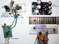
Simplistic Salas V1: built as p2p, no PCB, protoype
Shunt Revison 5c: built on PCB, prototype
SuperTeddyReg: PCB from Teddy Pardo, final version.
7805: built as final version, made in China
Shunt Revison 5c: built on PCB, prototype
SuperTeddyReg: PCB from Teddy Pardo, final version.
7805: built as final version, made in China
stormsonic, thank you for the report! BTW, for rev 5c did you use remote sensing?
Edit: also, I'm curious, did you try the regs with the superteddy in front? will you?
Edit: also, I'm curious, did you try the regs with the superteddy in front? will you?
Last edited:
yes, tried with remote sensing and without. No sonic difference in my ears 🙂
Used short wires, about 15 cm.
Raw DC input was 15V for all contestants.
Will configure STR for 15V output and connect infront of revision 5c and compare, but first must put together new power supply with 20 or 25V DC output.
Used short wires, about 15 cm.
Raw DC input was 15V for all contestants.
Will configure STR for 15V output and connect infront of revision 5c and compare, but first must put together new power supply with 20 or 25V DC output.
Last edited:
Good grouping. Short to the point descriptions. Will you put q7 for 1.1 at a point and review too?
P.S. Interesting how they keep the family genes from 1.0 to 2.5C even when boosted in all parameters. Weird that you get nothing with remote sensing. Ricardo wrote me just before that he got detail and stage and lead transient speed with first tests on 4 wire V1.
P.S. Interesting how they keep the family genes from 1.0 to 2.5C even when boosted in all parameters. Weird that you get nothing with remote sensing. Ricardo wrote me just before that he got detail and stage and lead transient speed with first tests on 4 wire V1.
Ricardo wrote me just before that he got detail and stage and lead transient speed with first tests on 4 wire V1.
Ricardo might have long wires to start with, then it makes sense that for him it would make a difference.
@stormsonic
I'd like to ask you a favour. When you got a few spare moments, could you please say a few things about your specific builds? Things like capacitor value and type, etc. Lots of people would surely like to know that. In other thread they shoot you for subjective assessments, but here I would like everybody to feel welcome. We do both science and art. 😀
Simplistic Salas V1: CCS MOSFET=IRFP9240, biased with 3 LEDs. 100uF Panasonic FC across LEDs. Voltage reference = 2 x LED + 200 Ohm trimmer. 4,7uF MKT across LEDs.
BC550C replaced with MPSA18. Shunt MOSFET=IRFP9240, output cap 4,7uF MKT (not on the picture).
Revision 5c LINK:
CCS MOSFET=IRFBC40, biased with 2 LEDs. Resistor R2=2k2 trimmer.
C3=100uF ELNA SILMIC II. R7=330 Ohm. R11=6K8. R9=6K8+4K7 trimmer for fine adjustment of output voltage.
Shunt MOSFET M1= CEB703AL (logic level). Output cap=4,7uF MKT.
C1=4,7uF MKT + 10uF ELNA SILMIC II (soldered under board). C1 have biggest sonic impact, anyone can tweak this capacitor as personal preference 🙂
@salas
will test further
@telstar
this 5V version tested with DAC
Last edited:
I don't know if 150mm leads are short or are long.
I don't know if the remote sensing should make an audible or measurable difference at this length of leadouts.
I do know that configuring the measuring bridge so that all 4 legs of the bridge are properly connected to each other is far too important to omit. Failure to configure the bridge and the errors resulting will be measurable and probably audible.
Stormsonic,
thanks for the testing and the report.
I do know that configuring the measuring bridge so that all 4 legs of the bridge are properly connected to each other is far too important to omit. Failure to configure the bridge and the errors resulting will be measurable and probably audible.
Andrew, what are you referring to when you say "properly connected?" Is there anything you think we didn't cover?
@telstar
this 5V version tested with DAC
Powering analog, digital or both circuits?
Hi Iko,
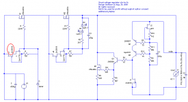
Yesterday a friend of mine had a look at your circuit and proposed some changes (improvements in his opinion).
This would be the modified circuit.
Please tell me what do you think and if you already tried some of those mods and with which results.
Also, the jfet circled in red seems to be of too low voltage - he suggested to replace it with a >30V jfet (suggestions?), also in your original circuit v5.
We want to use this cirtuit to give power to a LME49811 based VAS, with separate boards for channel and pos/neg - total of 4 regulators.
PS: Can you send me a message with yout email?
Attachments
- Status
- Not open for further replies.
- Home
- Amplifiers
- Power Supplies
- My take on a discrete shunt voltage regulator