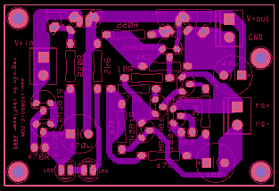
and 2N2819 (on PCB) => 2N3819 🙂
😀 yes, indeed, fixed now.
salas said:The vintage meter is way cool. Nice compact board too.
Thanks! Oh, the Avometer is very dear to me, a gift from a old professor. I use it all the time 🙂
Another Prototype
Gentlemen,
may I allow to introduce myself to this thread 🙂
I have been in discussion with ikoflexer to specify two regulators for 12v output, one at 500mA current limit, the other at 200mA. I cannot praise ikoflexer enough for his knowledge, willingness to share and help, and patience! Thank you so much!
I have just sourced the parts and will soon start building the prototypes. Will be pleased to report 🙂
Best,
Robert
@ikoflexer: I was intending to start out point-to-point, but would your new PCB also be a possibility for me?
Hi Robert,
Welcome to the thread.
Regarding the pcb, it's passed the "reality" test, but it may be a little while before it's ready for prime time. It's up to you.
I'll see if I get the time to try a 12V prototype soon, to help you with choosing R9 and R11.
Welcome to the thread.
Regarding the pcb, it's passed the "reality" test, but it may be a little while before it's ready for prime time. It's up to you.
I'll see if I get the time to try a 12V prototype soon, to help you with choosing R9 and R11.
Hi Relu,
hmm, in post#1 you had said that
Would you say (I know it can just be an estimate based on your experience) that point-to-point is substantially worse in this respect?
That's very kind of you that you want to support me with a 12V prototype! I have started out with R11 implemented as a trimmer, let's see where this gets me.
Many thanks
Robert
hmm, in post#1 you had said that
Low output impedance at high frequencies depends a lot on the actual implementation and board layout
Would you say (I know it can just be an estimate based on your experience) that point-to-point is substantially worse in this respect?
That's very kind of you that you want to support me with a 12V prototype! I have started out with R11 implemented as a trimmer, let's see where this gets me.
Many thanks
Robert
Hi Relu,
hmm, in post#1 you had said that
Would you say (I know it can just be an estimate based on your experience) that point-to-point is substantially worse in this respect?
I intended to make a pcb for those people who:
* have no time to pay much attention to layout, parts connections, etc.
* are beginners and want to get as close as possible to plug and play
* like to include something that looks neat in some other project
Point-to-point can be just as good IMHO, but let's face it, not everybody likes it.
That's very kind of you that you want to support me with a 12V prototype! I have started out with R11 implemented as a trimmer, let's see where this gets me.
No worries.
I just tried R9 = R11 = 8K2 and got 11.4V out. This should give you a value to start from. 🙂
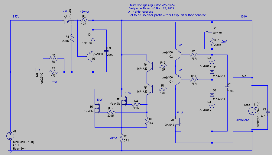
Quanghao asked for a high voltage regulator. He's a brave man.
I've built a similar version but not exactly this one below. These days I don't have a lot of time to be on the forum, so, Quanghao, if you don't really understand how to get this working, it might be better not to go for it.
NOTE: R2 might not have exactly this value of 10R. You need to adjust R2 for the desired current!!!
EDIT: each pair of zeners can be replaced with a resistor, of about 100k.
Last edited:
Board assembled 😀
Modification for 5V output of Version 5c
R9 = R11 = 5K6
R2 = 2K2 trimmer (to set shunt current)
All LEDs are not equal (different Vf) and all 2SK170 are not equal (different Idss), without trimmer R7 and R2 need some tweaking and experimenting for desired results. With trimmer is much easier 🙂
R10 = depends on particular J201. Smaller value = bigger current through voltage reference. 750R or 1K or 1K2 will be OK 🙂 My current is set to 200uA.
Initial impression: subtle improvement (better mids & highs) compared to Simplistic Salas V1 (without Q7 mod). More details, music flows more easy. Just initial impression, not final decision.
C1 = 4.7uF EPCOS MKT, C2 = 4.7uF EPCOS MKT (at output, not at load).
Last edited:
I'm curious how you modified it for 5V. Did you use a logic level shunt mosfet? (I hope you did.)
yes, good point.
IRFBC40 is on the edge here, Vgs is bellow treshold. For 5.5V output or more is OK, lower is possible only, when properly heated 🙂 But only low shunt currents 🙄
I have CEB703AL from old MSI6163 computer motherboard and some old 2SJ306 to experiment. Still working on this issue, to find easy available, cheap logic level N-channel MOSFET with high transconductance.
Last edited:
That source, you know who, has very cheap PHP3N20L. I got some and was going to try it at some point for the 5V version. If you stumble across something better, please let me know.
Yep, finished and tested. I ended up customizing all footprints and pads, lots and lots of tweaking, but the result is geared towards hand assembly, and I like that. Now I'm looking for a good pcb maker. Very few people showed interest in this project, so I might make only 100 pcs and keep them around for whoever asks.
Once you actually go live with PCB for IKO's discrete shunt reg. Things should go quickly. 🙂Very few people showed interest in this project, so I might make only 100 pcs and keep them around for whoever asks
Could be Bas 🙂
You might be more interested in the high voltage version. The rough concept you've seen already, but I think I'll put some work into making it more real, do testing, etc. I'd like to have a nice strong regulator for medium power tube amps, with nice low zout.
In the same time it'd be also nice to come up with a very low voltage version as well. Something that would be able to provide excellent performance at 2.5V - 6V output voltage.
@stormsonic
If you're around, I just want to make it clear. Revision 5c, the latest, will work really well for an output voltage greater than about 8 volts. The circuit just hasn't been optimized for low voltage.
Once you actually go live with PCB for IKO's discrete shunt reg. Things should go quickly. 🙂
You bet! 😎
Alright! Good news, the pcb is finished, and tested from beginning to end. Because it has more parts than other regulators and the layout is important it can be a bit more difficult to do point-to-point, but more experienced people will have not problem. There is a lot of info on how to get it working point-to-point. We've seen what happened with the pcb layout in the dcb1 case (a sad affair) so I'm reluctant to make public the pcb layout files. I'm going to order a number of boards with thick copper so they're good for higher current as well and thick pads so they can resist better to mods. This circuit will be excellent for output voltages of 8V up to about almost 30V (because of the 2n5088). It can be made to work with higher voltages too. The current limit depends on the mosfets used and he heat sink. I've had several amps going through it, and it get really hot. I've made allowances on the board for both to-220 and to-247 mosfets. Lots of different mosfets will work without any other modification. I just tried last night a 2sk2057 to-247 mosfet as the shunt device, worked like a charm.
I plan to write a comprehensive "how to" document that would be very helpful for people who are not very experienced and don't want to go through pages and pages in the forum.
I plan to write a comprehensive "how to" document that would be very helpful for people who are not very experienced and don't want to go through pages and pages in the forum.
Not yet audiojoy. Just as I was thinking of that I received tonight some very good feedback from a member from Europe who has built it recently. One of his comments was to make allowance on the board for a film cap in parallel with C1. Although I'd like to keep the board size small (it is 3x2 inches now, smaller than a credit card), a film cap there could make a difference, so I'll give it a try. Won't be too long to get it finished though.
- Status
- Not open for further replies.
- Home
- Amplifiers
- Power Supplies
- My take on a discrete shunt voltage regulator