Good guess, but I had in that position a higher hfe transistor and it didn't reduce the ripple. Still 
I'll try the hot iron experiment anyway 🙂
I'll try the hot iron experiment anyway 🙂
With V2 R5, do we need to select the right Idss for 2n3819, 2sk170 and J201? or any Idss will do?
So far I have found the output cap when placed at the load the circuit resonates while at the reg output it does not. Your latest suggestion confirmed that the cap should be at the output.
What if we bring the load right at the regulator output and solder everything in one board? In that case the output cap is basically at both the reg output and at the load. Would it resonate? I don't know. I guess the reduced inductance would reduce the chance of resonance, but then the reduced resistance would reduce the damping as well.
Anyone who has tested this please report the finding.
Quick answer because I have to go. 2n3819 should have Vgs(off) larger (about twice) than the 2sk170 that is below it. Idss does not matter greatly here; I tried to set it to about 0.5-1mA.
J201 Idss again, does not matter, choose G-S resistor to give you Id of about 15% of Idss. Easy to measure with a battery and DMM.
J201 Idss again, does not matter, choose G-S resistor to give you Id of about 15% of Idss. Easy to measure with a battery and DMM.
I have been satisfied with the performance of this regulator and is now already "settled". I am now finally getting back to working on my speakers by finalizing a few small items and redoing my measurements. Once the active circuit is re-adjusted based on the new measurements, I will destroy my current prototype used for measurement, and build 2 to 3 V2 R5 to power the active circuit. So I won't have anything to report to you in the coming a few weeks, as I am no longer working on the regulator.
Once the new speakers are completed, I will give the regulator a real test on this (I hope) reference level system, and may fine tune the implementation of the regulator to squeeze everything out of it.
Once the new speakers are completed, I will give the regulator a real test on this (I hope) reference level system, and may fine tune the implementation of the regulator to squeeze everything out of it.
Hey hifinutnut, thanks for doing all the tests and reporting back to us from the field. Good luck with your speakers and you're welcome back here anytime you feel like it.
@Iko
if you replace remaining MPSH81 (Q3) with 2N5087, what are your results? Better or worse? 🙂
if you replace remaining MPSH81 (Q3) with 2N5087, what are your results? Better or worse? 🙂
@Iko
if you replace remaining MPSH81 (Q3) with 2N5087, what are your results? Better or worse? 🙂
Worse. I said it above. 🙂 But hey, we're talking about microvolts here.
Now, does anyone know of an RF PNP with high hfe?
I'm tempted to try a darlington made out of two mpsh81 😀
latest version takes you to post 261 where the same link appears?
The second line of my signature takes me to post # 232
ikoflexer said:I will still use the 2N5087s that I have. I haven't tried BC560+BC560, but I have tried 2N5087+2N5087, and still the better one is to use MPSH81 on the bottom.I found. Maybe I need new reading glasses 🙄
I've tried in vain to find RF PNP transistors that could match the NPN equivalents.
Here's my current preferences for audio purposes:
Very Fast, low-gain: 2N5769/5771
Higher gain, still pretty fast: 2N4124/4126
If speed is not an issue I use the standards like the BC5xx series. I don't know what's possible with japanese transistors. There seems to be a paradox between Cjo and Tf. A transistor with 4pF Cjo may be rated 100MHz while one with 18pF may be rated 500MHz. So I suspect Cjo is a more important factor here...
- keantoken
Thanks kt. Now you see my problem 🙂 I could turn the circuit all the way around but that would require p-channel mosfets and that makes me less happy.
There are a few 2saXYXY parts that I've been meaning to try instead of the mpsh81, but it's just an idea at the moment. Even as it is, this regulator is very good I think. But there's always room for improvement.
The other area we can improve is line rejection, but I'm very tempted to do that via capacitor multiplier/gyrator before the reg. Paul Hynes (here going by the maximus user name) has suggested in another thread to somebody else (the Twisted Pear people) to use a cascode in the CCS. It's possible that in other circuits the cascode in the CCS provides a lot of improvement, but in this one here... I find it does not. The cascode in the CCS was one of the first things I tried. So, there...
A few to consider:
2sa1434 pnp high hfe 100MHz
2sa1697F pnp 300MHz hfe=160-320
2sa1749F pnp 400MHz hfe=160-320
2sa1875F pnp -- || --
2sc3820 pnp 200MHz high hfe=800-3200
How about 2SA3243?
http://www.toshiba.com/taec/components2/Datasheet_Sync//66/7771.pdf
Have you taken a look at what cascoding does to the line rejection of a series (BJT) capacitance multiplier? Somewhere around -108db I think. However there is an alternative... We can increase OLG in the CCS.
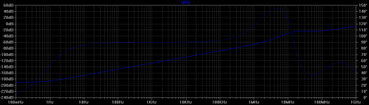
Try this. Homemodder has used this kind in his amplifiers (in low power places), except with BJT output. J1 at the bottom can be made a resistor... This design is really limited only by the current source used and the MOSFET's Cjo. Even a simple resistor gives good performance. (sorry, PSRR graph was taken with a perfect 2mA CCS, the actual graph bottoms at -120db with the current Jfet CCS)
- keantoken
http://www.toshiba.com/taec/components2/Datasheet_Sync//66/7771.pdf
Have you taken a look at what cascoding does to the line rejection of a series (BJT) capacitance multiplier? Somewhere around -108db I think. However there is an alternative... We can increase OLG in the CCS.
Try this. Homemodder has used this kind in his amplifiers (in low power places), except with BJT output. J1 at the bottom can be made a resistor... This design is really limited only by the current source used and the MOSFET's Cjo. Even a simple resistor gives good performance. (sorry, PSRR graph was taken with a perfect 2mA CCS, the actual graph bottoms at -120db with the current Jfet CCS)
- keantoken
Attachments
I got similar results without the ideal CCS. I've tried a lot of ideas in the CCS, cap multipliers, and gyrators. Just haven't posted them.
I decided to take time now to produce a proper PCB for v2, and stay away from other distractions. It's mostly finished, but I've been pulled away from it by various other things. It'll look something like this, still have to bring it up to date with release 5c. It's going to be 2.76'' x 2'' so it's not too large, but not miniature either.
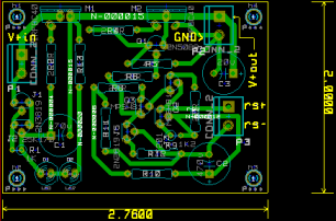
I decided to take time now to produce a proper PCB for v2, and stay away from other distractions. It's mostly finished, but I've been pulled away from it by various other things. It'll look something like this, still have to bring it up to date with release 5c. It's going to be 2.76'' x 2'' so it's not too large, but not miniature either.
Thanks kt. Now you see my problem 🙂 I could turn the circuit all the way around but that would require p-channel mosfets and that makes me less happy.
There are a few 2saXYXY parts that I've been meaning to try instead of the mpsh81, but it's just an idea at the moment. Even as it is, this regulator is very good I think. But there's always room for improvement.
The other area we can improve is line rejection, but I'm very tempted to do that via capacitor multiplier/gyrator before the reg. Paul Hynes (here going by the maximus user name) has suggested in another thread to somebody else (the Twisted Pear people) to use a cascode in the CCS. It's possible that in other circuits the cascode in the CCS provides a lot of improvement, but in this one here... I find it does not. The cascode in the CCS was one of the first things I tried. So, there...
A few to consider:
2sa1434 pnp high hfe 100MHz
2sa1697F pnp 300MHz hfe=160-320
2sa1749F pnp 400MHz hfe=160-320
2sa1875F pnp -- || --
2sc3820 pnp 200MHz high hfe=800-3200
Ixo,
These are worth a look. There are a whole series which include compliments.
The specs are very good for the right application.
Sanyo Pico Tr series
cheers
T
Ah, thank you Terry! Hm, surface mount. Not an obstacle, but it does change some of my plans a bit. If only I could find a good source for these; so far digikey and mouser say no such thing.
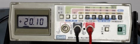
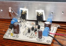
An update and a bit of good news. I've finished the pbc layout and built another prototype tonight using the board. The board is made around rev 5c posted before. I aimed for about 20V output, and fed it 45V DC because that's what I had around. The board has room for two LEDs, but I used just one because the voltage across it was about 2.1V. The following values I used in the real circuit:
R2 = 2K9
R7 = 470R
R9 = R11 = 15K
With these the output voltage was about 20V, and the current limit was about 500mA.
R2 = 2K9
R7 = 470R
R9 = R11 = 15K
With these the output voltage was about 20V, and the current limit was about 500mA.
Attachments
- Status
- Not open for further replies.
- Home
- Amplifiers
- Power Supplies
- My take on a discrete shunt voltage regulator