DoomPixie said:strange thing is.. when i added the bootstrap the hum actually decreased not increased :S
I think i'll try adding the ccs though.. 🙂
I'm off to have a play about in LTSpice! I'll let you know how i get on 🙂
Owen
Bootstrap is adding same sort of quality as a CCS
... we can say it is a more simple and easy way,
to make the current in the transistor more constant = less variations seen by the transistor
... in this case, the transistor between R1+R9 and R4
And, yes
it would also, make the transistor more isolated from V+, power supply
... and decrease hum
there is a capacitor that is blocking against V+
instead it follows the voltage of the Output.
This also means, that in some extreme situation
the voltage level at point in between those 2 resistors, R1/R9
can actually be higher than the V+ rail !!!
Because the voltage across a bigger capacitor stays almost same
.... it changes, loads and discharges very slowly.
Much much slower, than the variations of an AC sound signal
at for examples 1.000 periods per second. ( 1 kHz )
If using bootstrap, like Nelson Pass and Hugh 'AKSA' Dean
or the more complicated Constant Current Source = adding more transistors into a 'Simple Approach'
... is most often a matter of taste
... and also not overdoing (using CCS), when is not necessary
It will simulate, real test and perform very well either way!
Compared to plain resistors (see first version of DoomPixie amp)
both these methods of lower distortion
BootStrap & CCS
... are much Superior!
Regards
lineup
🙂
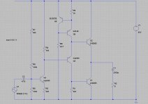
ok.. i played around a bit more in spice and have started to solder components together now and hopefulyl i should finish tommorow...
This is the ccs version modified for the components i have lying around.. R7 and R9 will be variable resistors, i just havent installed a model for a variable resistor in spice yet..lol. Only thing i wasnt sure about was Q6 but bc557b works in the sim and i dont see why it shouldnt in real life, i could be wrong though so please let me know if its just going to blow up..lol...
Cheers,
Owen
Attachments
Am useing same construction method again (by far my favorite) notice i havent added the piece of pcb as a ground plane yet.. I always solder the transistors together first and then add the ground plane as i am adding resistors.. Took the photo on top of a credit card size card thingie to ilistrate size.. 🙂
Owen
Owen
Attachments

Your circuit should work fine although I think you will find you need more resistance in the bias chain for q4 than spice shows, at least this has always been the case for my builds. 40 volt rail I would use 4 outputs or a really large heat sink. I would also add at least a small tab heatsink to all the transistors except the bc557.
I would also add at least a small tab heatsink to all the transistors except the bc557.hi
in your latest shematic, DoomPixie
I would add a cap, ~2.2-10 uF small elyt
- from junction between R6 and R7
- to ground, same as where R5 is attached to ground
This will block the very sensitive INPUT stage ( Base of Q4 )
from any hum from V+ rail
Most hum that we can actually hear, is coming from Input
just as any muic we can hear, comes from there, Too
-----------------------
I did show jerluwoo how to do this before
by recommend take a look at The Input of my Headphone amplifier.
... if he listened to me, I do not know 🙂
my Post #57 in this topic!
CLICK HERE and READ
My headphone amplifier = Class A simple but VERY Good!
Full details and very much description of details
is here:
Discrete Single End TRUE Class A HeadPhone Amplifier
Lineup Audio Lab - hifi headphone amplifier
Regards
lineup
🙂
You are quite correct Lineup. One has to feel a bit silly of the small details he forgets when hastely building things in the middle of the night because he cant sleep.
I use the ccs on the output stage because I have thouroghly tested and abused the circuit and know it will keep on going. I'm sure my speakers are an insanely varying impendance, 4 way passive crossover with 4 inductors and 5 caps in all, with a huge dip from about 100hz to 700hz. I generally bias for 5 ohms and never had any troubles.
I use the ccs on the output stage because I have thouroghly tested and abused the circuit and know it will keep on going. I'm sure my speakers are an insanely varying impendance, 4 way passive crossover with 4 inductors and 5 caps in all, with a huge dip from about 100hz to 700hz. I generally bias for 5 ohms and never had any troubles.
DoomPixie said:.......................This is the ccs version modified for the components i have lying around.. R7 and R9 will be variable resistors, i just havent installed a model for a variable resistor in spice yet..lol. Only thing i wasnt sure about was Q6 but bc557b works in the sim and i dont see why it shouldnt in real life, i could be wrong though so please let me know if its just going to blow up..lol...
Cheers,
Owen
Why would Q6 be at risk of blowing up? Does your sim show Q6's Vce, Ic, Pd at various operating conditions?
I reckon it has 1.2Vce across it. It is Q5 that has the higher Vce.
You may want to reduce Ic through Q6, it will operate well @ 1mA and probably quite a bit less if you care to experiment. It may sound better with a cap across C to E as well, again experimentation is required.
Quite correct AndrewT, the 557 is the only one he need not worry about, perhaps the max ce volage could be higher for a safety margin, since max ce is only 45 volts. All the rest will get quite warm if I remember correctly from the circuit I had running on the 40 volt rail. But as I said heat sinks all around and it will be fine. In the circuit I'm running right now on the little 18 volt rail, all the transistors except the mpsa are slightly warm to the touch, with the outputs being a bit warmer than the rest of course, even strapped to a heatsink that came from a 250 watt class b amp.
jerluwoo said:You are quite correct Lineup.
One has to feel a bit silly of the small details one forgets ,
when hastely building things in the middle of the night
because can not sleep.
.
😎
I just love the simplicity and 'clean-ness' of DoomPixie latest version schematic.
😎
Dont you agree, jerluwoo?!
This IS REALLY simple TRUE Class A - and as good as it can be!
Like AndrewT has figured out for us,
the next thing DoomPixie will have to do, is change some resistor values = optimize currents flow
-----------------------------------------------------------------------
I recommend this, Strongly:
1. Not to add any New Components, to mess this nice circuit up.
( except for the cap I mentioned )
2. Try out Best possible Values, of those Components in Circuit
( by using matematics, Ohms Law! and by listen to some suggestions from AndrewT
AndrewT is a teacher by profession
and in his free spare time hours, too; => They say a Tiger never lose his Stripes
and AndrewT has got long experience from electronic circuits! )
-----------------
Just add that little cap in input,
so that Base of input transistor
can not listen to V+ and to eventual ripple/hum from there.
In this case, the small capacitor acts as a
Constant Voltage Source
which actually is = Voltage Regulator.
.... at least for Constant AC Voltage .... and this is what matters here
Regards
lineup - Clean & good Circuits Lover
🙂
Agreed Lineup. Can go a step farther to simplify and use split rails and eliminate the output cap. Only change needed to do so is to route the resistor in the current source to ground instead of the bottom rail, although he may want to leave the cap until he's sure it wont drift away and put to much dc to his speaker. So far my little 18 volt circuit varies a little less than a volt from cold to warm, but once at operating temp. it doesnt budge at all.
Hey there,
It's a new day again and i have had some sleep 🙂
I Am thinking i may not use 40V rail in the final build, The prototypes are actually running on 24V!!
In final build i am thinking of useing 30V or 35V regulated supply..
The heatsinks i am useing are SMALL but are arranged in a wind tunnel formation with 80mm fans push pull running on 7V and they stay nicley warm to the touch! there is a thermal cut mounted on them for the power supply aswell just in case..
I have used the same heatsinks in a JLH Class A with 40V rails and 1.5A idles current and that amp never missed a beat 🙂
Lineup: I will add the capacitor you suggested lineup. and i will be adding some small pieces of copper to the BD140, MJE340, MJE350 (i actually ran out of mje's so im useing kse345/350 but i cant see the differance) just to make sure they stay nice and cool...
AndrewT: i didt think Q6 was going to blow up but better safe than sorry, i had been awake for 16hours when i chose that transistor, everyone makes silly mistakes sometimes..lol
jerluwoo: I never even bothered to check the bias of Q4 to be honest.. Completely slipped my mind i havent changed it since the last prototype though and that didnt blow up so it cant be "TOO" far off.. I will check it after i finish the next build though 🙂
Cheers,
Owen
It's a new day again and i have had some sleep 🙂
I Am thinking i may not use 40V rail in the final build, The prototypes are actually running on 24V!!
In final build i am thinking of useing 30V or 35V regulated supply..
The heatsinks i am useing are SMALL but are arranged in a wind tunnel formation with 80mm fans push pull running on 7V and they stay nicley warm to the touch! there is a thermal cut mounted on them for the power supply aswell just in case..
I have used the same heatsinks in a JLH Class A with 40V rails and 1.5A idles current and that amp never missed a beat 🙂
Lineup: I will add the capacitor you suggested lineup. and i will be adding some small pieces of copper to the BD140, MJE340, MJE350 (i actually ran out of mje's so im useing kse345/350 but i cant see the differance) just to make sure they stay nice and cool...
AndrewT: i didt think Q6 was going to blow up but better safe than sorry, i had been awake for 16hours when i chose that transistor, everyone makes silly mistakes sometimes..lol
jerluwoo: I never even bothered to check the bias of Q4 to be honest.. Completely slipped my mind
i havent changed it since the last prototype though and that didnt blow up so it cant be "TOO" far off.. I will check it after i finish the next build though 🙂Cheers,
Owen
A few microamps is all it takes to make it turn full on in some cases, may just add for the initial power on to be sure. Although it seems odd that the beta of the 340 would be a fair bit lower than the 31's I used. I have nearly 400k ohm in my bias chain for the correct offset at just 18 volts.
Need to wire in a socket to plug various vas transistors into to see how they sound and perhaps translate that into their diffent junction capacitance etc... oh just rambling on.
Need to wire in a socket to plug various vas transistors into to see how they sound and perhaps translate that into their diffent junction capacitance etc... oh just rambling on.
explain? Do you mean VOut? I am useing a 200K pot in the prototype instead of R7 so that its adjustable... I have however found that the V Out has to be a little under half the rail voltage for best results which isnt what i was expecting, i was expecting it to need to be slightly over.. *shrugs*
Owen
Owen
jerluwoo said:
So far my little 18 volt circuit varies a little less than a volt
from cold to warm,
but once at operating temp,it doesnt budge at all.
.
Very Typical for Class A 🙂
And when, after ½-1 hour, everything has settled in a warm state,
they usually stay Rock Solid around 0.0x Volt at output.
Amps can be effected by other things
than by temp changes by high output power levels.
An amplifier that 'heats itself up' from inside
is actually less sensitive to eventual room temperature changes,
like for example a cold temporary wind from an open window.
While a 'colder amp' Class B / AB will be more sensitive to surrounding temp.
It is something like when it is cold outside in winter.
When you sit doing nothing, you will easily freeze ..brrrrr😀
But if you are busy showling snow with a spade,
to clean path to your front door of your house,
you will soon think it is too hot
and so you will have to button up your clothes a bit
to cool off.
😎
Regards
lineup
🙂
Yup vout is what i mean. If you dont get enough resistance in that bias chain there in the front the vas transistor will pull vout to ground or close enough. Why is this a bad thing you ask? In this circuit, if the voltage at the base of the phase splitter transistor,q3 in your schema, goes to the positive rail, the current through the output goes to zero. Guess what happens when it is pulled to ground. So it is better by far to not be able to turn q1 on full tilt and take a bit away than to have the base of q3 pulled to ground.
This doesnt hold true using a split rail as it is bad if it goes either direction.
I too think vout a little under half to be odd, as the negative side on all mine has clipped first.
So it is better by far to not be able to turn q1 on full tilt and take a bit away than to have the base of q3 pulled to ground.This doesnt hold true using a split rail as it is bad if it goes either direction.
I too think vout a little under half to be odd, as the negative side on all mine has clipped first.
i have been haveing problems with the positive half of the output clipping, i just checked it all again though and with the ccs the problem has gone away and your right, in this circuit haveing VOut at around 23V seems to work best.. I was getting mixed up between the circuit as it is now and how it was before i added the ccs..
However i have had both versions of this circuit running in the flesh (not in sim) and i havent seen a problem yet with useing the 100K resistors and a 100K Variable resistor for adjusting VOut.. I start the amp up for the first time with 100K either side and then i set bias up but leave it a little under what i want and then set VOut and let the amp warm up for about an hour playing music.. then i go back and check it all again and if it all looks good reset bias and vout to the desired levels and play music for an hour or so before going back and checking for a final time!
Owen
Gratz, DoomPixie. I was just trying to be cautious and save ya some transistors. I'm glad it works correctly for you. Let us know how it sounds after it breaks in a bit.
So anyone out there that has some proper test equipment out there care to throw one of these together and post some numbers for us? Distortion, power out etc.. I've always been really interested to find out these things since I first built the circuit. I can sim all that but it isnt the same.
Hi, 😀DoomPixie said:ok.. i played around a bit more in spice and have started to solder components together now and hopefulyl i should finish tommorow...
This is the ccs version modified for the components i have lying around.. R7 and R9 will be variable resistors, i just havent installed a model for a variable resistor in spice yet..lol. Only thing i wasnt sure about was Q6 but bc557b works in the sim and i dont see why it shouldnt in real life, i could be wrong though so please let me know if its just going to blow up..lol...
Cheers,
Owen
Only a question,
thermal runaway for Q1 and Q2 (2N3055) ?
In general the spice doesn't warn any thermal runaway.
If the end-stage bjt tend to increase the quiescent current
I suggest a Emitter resistor.
thermal runnaway hasnt proved to be a problem.. it has been running pretty much 7 hours solid today now and the bias is actually down a little now from where i set it..
My class A amps are all fan cooled and i have thermal cut outs ont he heatsinks just in case, i find they usually react fast enough to avoid catastrophy, they saved my jlh a couple of times when i forgot to plug the fans in after all.. lol .
Owen
My class A amps are all fan cooled and i have thermal cut outs ont he heatsinks just in case, i find they usually react fast enough to avoid catastrophy, they saved my jlh a couple of times when i forgot to plug the fans in after all.. lol .
Owen
- Status
- Not open for further replies.
- Home
- Amplifiers
- Solid State
- My simple class a approach