JasonL said:Do you have nay more boards ? are these designed for the gain clone ? Or something else ? Id like to buy a few boards for my gain clone if that is what these are for. ?
the regulator board purpose for general use.it can be used in all standard LM3875/3886 IGC or NIGC designs.Even a solid state power amp,such as JLH.
hrer is 3886igc and regulator PCB boards group order page:http://www.diyaudio.com/forums/showthread.php?s=&threadid=41746
I will accept order from today till October 10.
digi
Digi,
Have you tried your circuit? How does it sound? Please let me know what the advantages are when using your regulator. I'm probably interested in a set of these.
Have you tried your circuit? How does it sound? Please let me know what the advantages are when using your regulator. I'm probably interested in a set of these.
digi01 said:
the regulator board purpose for general use.it can be used in all standard LM3875/3886 IGC or NIGC designs.Even a solid state power amp,such as JLH.
The LM338 regulator can be used in non-class-A JLH designs, but I am not so sure on class-A power amps. How much are the demands in current for JLH class-A amps?
Carlos
carlmart said:
The LM338 regulator can be used in non-class-A JLH designs, but I am not so sure on class-A power amps. How much are the demands in current for JLH class-A amps?
Carlos
The regulator PCB is based on LM338,it is capable of supplying in excess of 5A over a 1.2V to 32V output range.
A 10 Watt class A JLH,the Iq usually set at 1.2A, 27V.it can work fine.
http://www.diyaudio.com/forums/showthread.php?s=&threadid=3075&highlight=jlh
You can find more detail about LM338 psu and JLH amp at here:
http://www.tcaas.btinternet.co.uk/jlhnewps.htm
digi
Member
Joined 2002
Thanks Digi i got mine a few days ago from Dave... I got 8 boards. Just got to order some parts now. : O ) They look GREAT!!...
Do you know about any other deviced being able to drop in and get a higer voltage ?
Jason..
Do you know about any other deviced being able to drop in and get a higer voltage ?
Jason..
JasonL,Thank your appreciating 🙂
LM338 can be suitable now,it's input voltage is 32V(max =40v).LT1083 is all right,but expensive.If the amp need high current and high voltage,It is more worthwhile that I think is unregulaotr method.
the board be able to drop in LM317 chip for peramp or headphone amp using.
btw,attach the board via pad assign.it can be hook wires for unregulaotr & regulaotr using.
Attachments
IIRC the LM338 32V limitation is how much it can *drop* (difference between input voltage and output voltage).
So, it is suitable for high(er) voltage just fine. I think. 😉 I never really paid attention to whether it has a maximum since I have no projects that would need anything particularly high at the moment.
C
So, it is suitable for high(er) voltage just fine. I think. 😉 I never really paid attention to whether it has a maximum since I have no projects that would need anything particularly high at the moment.
C
digi01 said:JasonL,Thank your appreciating 🙂
LM338 can be suitable now,it's input voltage is 32V(max =40v).LT1083 is all right,but expensive.If the amp need high current and high voltage,It is more worthwhile that I think is unregulaotr method.
the board be able to drop in LM317 chip for peramp or headphone amp using.
btw,attach the board via pad assign.it can be hook wires for unregulaotr & regulaotr using.
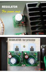
so to make sure i understand you. You can make it a regulated PSU or unregulated, as you show in the pic?
sorry for delay,I am on holidays and just come back.
Yes,I have set up a couple of unregulated via pad on the board.
Observing my pcb carefully,you will find its layout very ingenious.
H.B.
You can make it a regulated PSU or unregulated.
Yes,I have set up a couple of unregulated via pad on the board.
Observing my pcb carefully,you will find its layout very ingenious.
H.B.
for somebody asks for print edition,
This project is a double layers design,I have set up via pad for tight the component legs.the track of circuit has only taken up bottom layer.If you want to do it yourself circuit board, here is the printable file.
This project is a double layers design,I have set up via pad for tight the component legs.the track of circuit has only taken up bottom layer.If you want to do it yourself circuit board, here is the printable file.
Attachments
digi01 said:high detail pdf file,feel free to use it.
enjoys
digi
digi,
Did you intend for the .pdf to be sized for actual size printing? If so you may have to recreate it.
It is very large if printed, filling the whole paper I think. Kind of neat to imagine components that big. 🙂
Hi Zang-
In post # 2 you have a picture of the regulator board "with" regulator installed.
What component is that?
I ordered the LM338 regs to build mine but I think they are to-220 package, and the one in your picture looks like TO-3P or TO-247.
If it is the 108x chips why is that one so much larger yet not handle as much current as the 338?
Which chip do you recommend for the highest steady current draw? No worries on heat, I will have plenty of heat sinking.
Sorry to ask such a simple question, but I just have a hard time believing that the little TO-220 chip handles more current than the bigger 108x chips.
PS- I have at least 5 prs of your regulator boards and I need to get them finished but want to drop in the best part...
- Status
- Not open for further replies.
- Home
- Amplifiers
- Chip Amps
- my regulator pcb