Hi all
starting from this 2 thread
http://www.diyaudio.com/forums/multi-way/288470-build-very-slim-speakers.html
http://www.diyaudio.com/forums/multi-way/289110-cheap-woofer-high-spl.html
I'm trying to create a new project with SPL around 88db with little volume (around 14/16 l) and budget around 200€.
I select following speaker:
1) woofer is RS180P-8
2) tweeter is Vifa BC25TG15
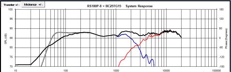
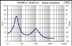
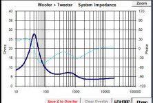
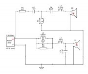
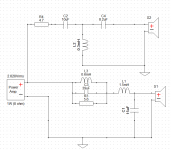
The lowpass is a simple 2 order with L = 1,4mH (R around 0,5ohm) and C = 8,2uF.
The highpass is a simple 2 order with C = 10uF and L = 0,4mH (R around 0,3ohm). I add an LPAD with R1 = 1,5ohm and R2 = 2,7ohm.
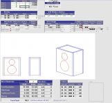
The box will be vented. I will use MDF depth 1,9cm, external dimension WxHxD will be 30x34x24 and port tube diameter will be 5 cm and lenght 8 cm (frequency about 54Hz).
I use Passive Crossover Designer 7 to obtain simulations attached.
What do you think about this project? Any suggestion will be appreciated.
Thanks
starting from this 2 thread
http://www.diyaudio.com/forums/multi-way/288470-build-very-slim-speakers.html
http://www.diyaudio.com/forums/multi-way/289110-cheap-woofer-high-spl.html
I'm trying to create a new project with SPL around 88db with little volume (around 14/16 l) and budget around 200€.
I select following speaker:
1) woofer is RS180P-8
2) tweeter is Vifa BC25TG15
The lowpass is a simple 2 order with L = 1,4mH (R around 0,5ohm) and C = 8,2uF.
The highpass is a simple 2 order with C = 10uF and L = 0,4mH (R around 0,3ohm). I add an LPAD with R1 = 1,5ohm and R2 = 2,7ohm.
The box will be vented. I will use MDF depth 1,9cm, external dimension WxHxD will be 30x34x24 and port tube diameter will be 5 cm and lenght 8 cm (frequency about 54Hz).
I use Passive Crossover Designer 7 to obtain simulations attached.
What do you think about this project? Any suggestion will be appreciated.
Thanks
Attachments
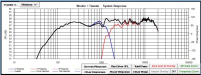
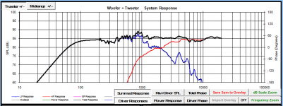
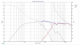
You have made a mistake preparing your frd file. First you
load the frd file you got from Dayton Audio (0 deg) to a
spreadsheet (Response Modeler) and turn the phase button Off.
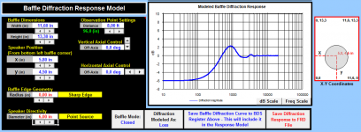
You will let the spreadsheet calculate the phase after you add
the modeled box response (Box Response Model) and baffle
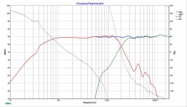
diffraction response to your initial frd file. With just one RS 180P-8
you can't have much SPL as you wish. This is simmed response
of your driver in a BR of 15 litres, Fb=50 Hz and on a baffle
of 7,5" by 15".
load the frd file you got from Dayton Audio (0 deg) to a
spreadsheet (Response Modeler) and turn the phase button Off.
You will let the spreadsheet calculate the phase after you add
the modeled box response (Box Response Model) and baffle
diffraction response to your initial frd file. With just one RS 180P-8
you can't have much SPL as you wish. This is simmed response
of your driver in a BR of 15 litres, Fb=50 Hz and on a baffle
of 7,5" by 15".
Attachments
Not sure I like that dip between 300Hz and 1k. Could you not use a smaller inductor on the woofer and a bigger shunt cap?
Only one? Good! This is my first project, I read several guide but I have no clear all step 😀You have made a mistake preparing your frd file.
First you load the frd file you got from Dayton Audio (0 deg) to a
spreadsheet (Response Modeler) and turn the phase button Off.
You will let the spreadsheet calculate the phase after you add
the modeled box response (Box Response Model) and baffle
diffraction response to your initial frd file.
How?
With just one RS 180P-8
you can't have much SPL as you wish. This is simmed response
of your driver in a BR of 15 litres, Fb=50 Hz and on a baffle
of 7,5" by 15".
I didn't understand why...

Not sure I like that dip between 300Hz and 1k. Could you not use a smaller inductor on the woofer and a bigger shunt cap?
Thabks for suggestion.
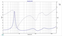
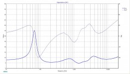
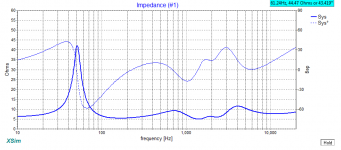
I change lowpass value using L = 1,5mH (0,65 ohm) and C = 22uF and highpass value using C = 22uF and L = 0,5 (0,49 ohm) and obtain attached SPL and imoedence graphs.
Attachments
The final FR of a driver depends on the baffle geometry and driver location, whose effects are baffle step and diffraction. So before you can use a crossover simulator you need to have or a measured FR or a simulated ***for your intended baffle/box*** FR. And remember also to add valid phase to both FR and impedance.
A step by step approach is shown here: http://audio.claub.net/software/DaveDalFarra/Simple%20Loudspeaker%20Design%20ver2.pdf
And here you can find the SW needed: software
Ralf
Edit: I see you posted another simulation. It is wrong as is the first you posted. And I'm pretty sure the tweeter can't sustain a so low crossover point.
Last edited:
ggerla,
There is a guide by Dave dal Farra that might help you with your sims.
In Jeff's spreadsheet Response Modeler read the user guide. Very helpful.
Your woofer has got sensitivity around 88 dB only because the measurement
from manufacturer was performed in an "infinite baffle" where you don't
have a loss of SPL unlike in full space or when you put it in a box and
place the box in a room away from the walls. As a rule of thumb, decrease
the SPL value you get with TS parameters by 6 dB and you end up with
a value of SPL that you can count on.
Your simulated response is as if you were to keep these drivers built into a wall.
IMHO, in a typical room, with speakers not very far from any wall and boundaries, it is better not to use the full BSC i.e. 6 dB, but a lower value, around 3-4 dB. You end up with a sensitivy of 84-85 dB, but not more.
Ralf
Ralf
IMHO, in a typical room, with speakers not very far from any wall and boundaries, it is better not to use the full BSC i.e. 6 dB, but a lower value, around 3-4 dB. You end up with a sensitivy of 84-85 dB, but not more.
Ralf
Ok, i understand that i have change my simulation. I try to study your suggestion during next days.
But... If i cannot have more than 84-85db, I Can use classix II without change. Or not?
Thanks
ggerla,
I think simulations are good, but keep in mind it's best to build the cabinet and then measure the drivers in place before committing to crossover parts. 🙂
Simulations help you pick your cabinet dimensions, and see if the drivers would line up reasonably well but in the end the measured real life data is best. For instance, what is missing so far is the acoustical distance between drivers. When yo add that (1.2 to 1.4" in a 2 way is typical) then your whole crossover design goes to hell. 😀
I like to use XSim to create the crossover based on actual measurements.
Best,
Erik
I need help
Hi all
after your suggestion I make several simulation and several study.
Basing on zaph's project "The Chameleon"
SB Acoustics 2-Way Title Page
and use this guide
https://sites.google.com/site/undefinition/simulated-measurements
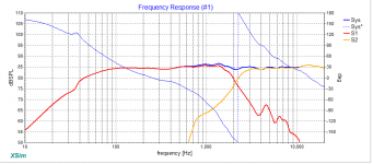
To increase SPL I decided to use woofer SB17NRXC35-8 and tweeter SB26STC-C000-4 and I also changed in a sealed box of about 12,5l. External dimensions are WxHxD = 29x34x20
I import frd and zma file using spl copy. Then using Response modeler 3.01, I simulated box and diffraction.
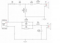
At the end I use passive crossover designer to calculate crossover parts. I try to make it easy with 2 order for both. Low pass L = 2mH and C =8,2uF. High pass C = 6,8uF and L = 1,2mH
I attached the result.
I didn't understand why zaph's response is more smooth. I have some ripple between 200Hz and 1kHz. I think that I'm not able to do better.
What do you think about this project?
Hi all
after your suggestion I make several simulation and several study.
Basing on zaph's project "The Chameleon"
SB Acoustics 2-Way Title Page
and use this guide
https://sites.google.com/site/undefinition/simulated-measurements
To increase SPL I decided to use woofer SB17NRXC35-8 and tweeter SB26STC-C000-4 and I also changed in a sealed box of about 12,5l. External dimensions are WxHxD = 29x34x20
I import frd and zma file using spl copy. Then using Response modeler 3.01, I simulated box and diffraction.
At the end I use passive crossover designer to calculate crossover parts. I try to make it easy with 2 order for both. Low pass L = 2mH and C =8,2uF. High pass C = 6,8uF and L = 1,2mH
I attached the result.
I didn't understand why zaph's response is more smooth. I have some ripple between 200Hz and 1kHz. I think that I'm not able to do better.
What do you think about this project?
Attachments
-
SB17NRXC35-8_impedence_inbox_phase.txt13.1 KB · Views: 78
-
SB17NRXC35-8_inbox_phase.txt13.6 KB · Views: 62
-
SB26STC-4_impedence_inbox.txt15.1 KB · Views: 77
-
SB26STC-4_inbox.txt12.8 KB · Views: 81
-
 finalSPL.png41.2 KB · Views: 450
 -
 boxycad.png36.1 KB · Views: 457
 -
 woofer_diffraction.png47.6 KB · Views: 440
THe problem is the original design uses a rather low - Q 4th order filter which takes care of the irregularities in the crossover.
I don't knwo about the tools you are using, but usually in XSim, after I get close enough I tweak one or the other of the 2nd order parts, altering the Q or slope until they match perfectly. I'm not sure if this will be enough to resolve the issue. If it is not then the solution is simple: Add more parts!
Consider the original design's LR4 crossovers, or add a notch filter in the woofer to smooth out the roughness.
Also, do you have the acoustic distance considered already? Have you measured it?
Best,
Erik
Last edited:
THe problem is the original design uses a rather low - Q 4th order filter which takes care of the irregularities in the crossover.
I don't knwo about the tools you are using, but usually in XSim, after I get close enough I tweak one or the other of the 2nd order parts, altering the Q or slope until they match perfectly. I'm not sure if this will be enough to resolve the issue. If it is not then the solution is simple: Add more parts!
Consider the original design's LR4 crossovers, or add a notch filter in the woofer to smooth out the roughness.
Thanks Erik for suggestion. I will try to add components...
Also, do you have the acoustic distance considered already? Have you measured it?
Room is 4,2m x 3m. I will put speakers on shelf at about 1,5m from floor along largest wall. I will listen music on my sofa at about 2m from speaker.
I don't hnow how to use this information for simulation. I think that I have to set "driver horizontal Offset" and "driver vertical Offset" in PCD but I'm not sure on result. Can you give some link or some suggestion?
Hi all
after your suggestion I make several simulation and several study.
Basing on zaph's project "The Chameleon"
SB Acoustics 2-Way Title Page
and use this guide
https://sites.google.com/site/undefinition/simulated-measurements
To increase SPL I decided to use woofer SB17NRXC35-8 and tweeter SB26STC-C000-4 and I also changed in a sealed box of about 12,5l. External dimensions are WxHxD = 29x34x20
I import frd and zma file using spl copy. Then using Response modeler 3.01, I simulated box and diffraction.
At the end I use passive crossover designer to calculate crossover parts. I try to make it easy with 2 order for both. Low pass L = 2mH and C =8,2uF. High pass C = 6,8uF and L = 1,2mH
I attached the result.
I didn't understand why zaph's response is more smooth. I have some ripple between 200Hz and 1kHz. I think that I'm not able to do better.
What do you think about this project?
well...
i make some progress... now the problem is the cost. 🙁
I have about 55€ for 2 low pass part. This is because high value of cap and low resistor value of coil...
anyone has suggestions?
Thanks
Attachments
Hi all
I decided to build this project. I'm ready to order all component on loudspeakerfreaks. Please can you check order list? I forgot something?
2 x SB17NRXC35-8SB acoustics 6 inch midwoofer
2 x SB26STC-C000-4 SB acoustics 1 inch tweeter soft dome
2 x 001-0264Jantzen 10,00 µF cross cap Vdc 400 volt 5%
2 x 002-0784Ceramic 5,60 Ohm resistor 10W 5%
2 x 001-0280Jantzen 39,00 µF cross cap Vdc 400 volt 5%
2 x 001-0274Jantzen 27,00 µF cross cap Vdc 400 volt 5%
2 x 001-0262Jantzen 8,20 µF cross cap Vdc 400 volt 5%
2 x 000-2018Jantzen 0,800 mH iron core coil Cu 1,2 (17AWG) Rdc 0,170 Ohm
2 x 000-2376Jantzen 1,000 mH iron core coil Cu 1,2 (17AWG) Rdc 0,185 Ohm
2 x 000-1234Jantzen 0,100 mH air core coil Cu 1,0 (18AWG) Rdc 0,120 Ohm
2 x 000-1279Jantzen 0,250 mH air core coil Cu 1,0 (18AWG) Rdc 0,223 Ohm
2 x 002-0805Ceramic 12,00 Ohm resistor 10W 5%
2 x 012-0310Loudspeaker terminal with gold plated contacts
2 x SPCBL-OFC-4.0Loudspeaker OFC cable 2 x 4mm (per meter)
thanks
I'm getting different results with your XO filter values
and drivers in phase.I have used 1/6th octave smoothing
for a woofer. Sealed box of 11 litres.
edit: You forgot to calculate phase for SB26.frd
and drivers in phase.I have used 1/6th octave smoothing
for a woofer. Sealed box of 11 litres.
edit: You forgot to calculate phase for SB26.frd
Attachments
Last edited:
I'm getting different results with your XO filter values
and drivers in phase.I have used 1/6th octave smoothing
for a woofer. Sealed box of 11 litres.
edit: You forgot to calculate phase for SB26.frd
Hi Lojzek
thanks for your patience.
For woofer I compared my frd file with one downloaded from Zaph audio. I saw that both have same trend at all frequences, but Zaph one is more smooth than mine. So I used frd and zma files from Zaph.
About the tweeter, probably I make an error on phase calculation. I redo the work. In attach the result. I have to change a lot resistance and inductance values of high pass.
Now it seems good. Wdyt?
Attachments
Last edited:
I think that you'd be better off if you had raised L1 to about 1,5 mH
and lowered the C1 to15 and C3 to 30. Loose the L4. This small
HF rise will dissapear as soon as you move a bit off-axis. This is all
theoretically speaking for a speaker in free space.
and lowered the C1 to15 and C3 to 30. Loose the L4. This small
HF rise will dissapear as soon as you move a bit off-axis. This is all
theoretically speaking for a speaker in free space.
I think that you'd be better off if you had raised L1 to about 1,5 mH
and lowered the C1 to15 and C3 to 30. Loose the L4. This small
HF rise will dissapear as soon as you move a bit off-axis. This is all
theoretically speaking for a speaker in free space.
Ok about L4 remove.
For low pass suggestion, this introduce a decreased curve between 200Hz and 700Hz of about 1db. Do you mean that this is negligible?
I try also another change, leaving C3 to 39 but reducing L3 to 0,6mH (in attach). This reduces decreasing of your suggestion but introduce a little ripple at 4kHz.
Attachments
- Status
- Not open for further replies.
- Home
- Loudspeakers
- Multi-Way
- My personal 2 way project