Why don't you choose a driver with a really low Fs ? In my opinion pro drivers don't fit. It will be difficult to go as low as 25Hz if your driver has a higher Fs. You should choose hifi drivers or car drivers( Notice a lot of car driver are design to work in free air 😉 )
For example
Dayton Titanic MKIII
DaytonRSS390HF-4
Aurasound NS18-992-4A.pdf
For example
Dayton Titanic MKIII
DaytonRSS390HF-4
Aurasound NS18-992-4A.pdf
Stig-Erik, you are a great inspiration for many of us, I'm certain.
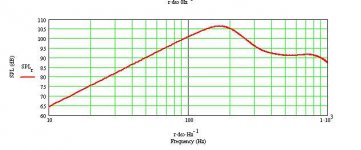
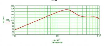
Here is the simu for the 21" in the H-frame 22 x 22 x 22 inches that I mentioned earlier. Crossover is set to 60 Hz 24 dB/octav Linkwitz-Riley. First 1 watt response:
It will be sufficient to apply dipole 6 dB correction from 50-60 Hz.
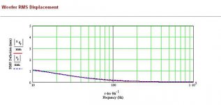
Next picture is of cone movement when 100 dB SPL is reached at 25 Hz:
Quite impressive ! 🙂
/Erling
Here is the simu for the 21" in the H-frame 22 x 22 x 22 inches that I mentioned earlier. Crossover is set to 60 Hz 24 dB/octav Linkwitz-Riley. First 1 watt response:
An externally hosted image should be here but it was not working when we last tested it.
It will be sufficient to apply dipole 6 dB correction from 50-60 Hz.
Next picture is of cone movement when 100 dB SPL is reached at 25 Hz:
An externally hosted image should be here but it was not working when we last tested it.
Quite impressive ! 🙂
/Erling
Nice! I could go with a slightly larger H-baffle than the one you simulated here.
Is it possible to show the excursion all the way down to 20 Hz? The graph just goes through the roof here.... 🙂
Is it possible to show the excursion all the way down to 20 Hz? The graph just goes through the roof here.... 🙂
As said before, better wider and higher than deeper, but I don't think the difference will be very great. I'm afraid that the whole diagram from MJK's model is copied, so you will have to extrapolate yourself.
/Erling
/Erling
I'm afraid that the whole diagram from MJK's model is copied, so you will have to extrapolate yourself.
/Erling
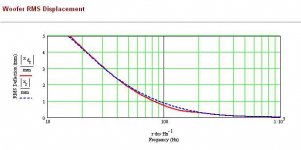
A linear extrapolated Xmax seems low.
Attachments
I'm afraid that the whole diagram from MJK's model is copied, so you will have to extrapolate yourself.
Erling,
you can scale the diagrams at will. If you double click on the lone "5" left to the y-axis, you can edit it to the value you want. Same for the lower value "0" and the x-axis.
Also, consider how MJK calculates "rms displacement": to convert Xmax (a peak to peak value), divide by 2 (to get the peak value), then multiply by .707 to get the rms value. For a woofer with 18mm Xmax, the 'maximum' rms displacement would be 6.4mm.
There are two important points about these type of calculations - first, each company defines/measures/estimates Xmax different ways - so it is impossible to know if it represents reality. The other point is that music isn't pure tones, and so music may be played much louder than just pure test tones. As a final check, I always measure non-linear distortion of the final design at high levels (although this is tough in the bass for a number of reasons).
So I consider these type of calculations rough estimates, but still useful.
When installed onto a baffle, the fs of the woofer (or now the system) drops.
The fs of my woofer is measured 30Hz free air / 20Hz on baffle. These are not very precise numbers, but close enough.
The fs of my woofer is measured 30Hz free air / 20Hz on baffle. These are not very precise numbers, but close enough.
Okay, here are the sims I did.
First a couple of things - MJK's models only allow you to use one driver per H-frame, so you have to estimate what happens when you add another. Basically add 3-6dB to the SPL graph. It depends on how you wire the drivers and if you use one or two amps (Re of 5.3 is low to put them in parallel, but could happen).
Also, the there will be two H-frames, so add another 6dB, for a total of 9-12dB more than what the graphs show.
I simmed the Beyma 18P1200ND. Its spec sheet says Xmax is 9.5mm, and that is equal to 3.4mm rms displacement, which is how Martin shows it. Again, caveats apply here.
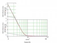
So one set of graphs is with 1W input, the other was with 32W input, which is what would get you to Xmax at about 25Hz. I think the graphs look promising - like 90dB/1W/1m at 25Hz! You will reach 'Xmax' at about 106dB SPL at 25 Hz. But the max spl at higher frequencies will be much higher.
First a couple of things - MJK's models only allow you to use one driver per H-frame, so you have to estimate what happens when you add another. Basically add 3-6dB to the SPL graph. It depends on how you wire the drivers and if you use one or two amps (Re of 5.3 is low to put them in parallel, but could happen).
Also, the there will be two H-frames, so add another 6dB, for a total of 9-12dB more than what the graphs show.
I simmed the Beyma 18P1200ND. Its spec sheet says Xmax is 9.5mm, and that is equal to 3.4mm rms displacement, which is how Martin shows it. Again, caveats apply here.
So one set of graphs is with 1W input, the other was with 32W input, which is what would get you to Xmax at about 25Hz. I think the graphs look promising - like 90dB/1W/1m at 25Hz! You will reach 'Xmax' at about 106dB SPL at 25 Hz. But the max spl at higher frequencies will be much higher.
Attachments
Cuibono,
Thank you!
Beyma claimes that the Xmax of 18P1200nd is 19 mm peak-peak (+/- 9.5 mm), so I would think RMS displacement is to be doubled - 6.7 mm. That would add an other 6 dB. Am I right?
106 dB @ 25 Hz is not bad at all, should be sufficient for my needs.
Thank you!
Beyma claimes that the Xmax of 18P1200nd is 19 mm peak-peak (+/- 9.5 mm), so I would think RMS displacement is to be doubled - 6.7 mm. That would add an other 6 dB. Am I right?
106 dB @ 25 Hz is not bad at all, should be sufficient for my needs.
One additional suggestion, if you still have spare time and energy for experiments:
Try a second pair of nude 21" placed behind the others - half way in between to the front wall and let them come in at roughly half your XO at 6dB/ oct
should do for a quick try though I use the split power technique (parallel shunt capacitor) - shelfing the front pair by -6dB accordingly
Works pretty well for me at the moment...
This balances excursion and also seems to have a minor but positively audible influence in exciting room modes.
According to JohnK and my own lousy simus the two dipoles are more or less acting like one.
Michael
Last edited:
Rudolf, you may very well be right about Martin's presentation, but I seemingly only can change the grid resolution not really the absolute scale ?
I think it would be best if Martin himself could explain his use of the RMS statistic. Notation is more pointing to Absolute Value. Cuibono's reasoning I think is more apporpiate with regard to electrical calculations with sine waves.
To give an example the RMS statistic for an observation series like:
+ 5, -5, + 5.2, - 5.1 would be SQR( (5^2 + 5^2 + 5.2^2 + 5.1^2)/4) = 5.076
MJK also has a guide how to use two speakers in his models: http://www.quarter-wave.com/General/Two_Drivers.pdf . I have tested this with the OB models for one and two bass units and the two methods produce identical results for parallel units. My conclusion is that it is alright to model two identical units as a compound unit.
/Erling
Last edited:
Stig Erik, you are amazing - would be great you could do a 0 15 30 45 polar measurement for each setup for us to compare.
Below my polar measurements of a 8" and 6" in a 30cm / 12" wide baffle and without any baffle taken indoor with a gating of ~4ms (so forget anything below ~300Hz).
8" is the Jantzen JA8008
6" is the B&C 6PEV13
To make even more clear what Sitg Erik and Cuibono have outlined I normalised FR to on axis response.
What we see is a virtually perfect equalised an axis response and the corespondent polars at 10, 20, 30, 40, 50, 60 deg

Above the 8" Jantzen JA8000 in a 30cm / 12" wide OB

Above the 8" Jantzen JA8000 in a 30cm / 12" without any baffle

Above the 6" B&C 6PEV13 in a 30cm / 12" wide OB

Above the 6" B&C 6PEV13 in a 30cm / 12" without any baffle
Uups – the top end polar's are way better without a baffle (as already been said)
Comparing the two different speaker size' - both without any baffle - it comes as a surprise that the 8" is *smoother* (up to ~2500kHz) than the 6" !
seem to be perfectly reasonable to still cross the 8" at ~ 1500Hz
Comparing the two speaker in the same baffle the 8" speaker clearly wins by a large margin.
To be fair, we possibly would have to measure the 6" in a proportionally smaller baffle.
Also can be seen the dipole –6dB at 60deg isn't true for *both* speakers. I think this is due to the same reason as 90deg never measures 0dB – simply the asymmetry due to the motor structure.
One conclusion seems to be a safe bet, taking a smaller speaker does not necessarily turn out in smoother top end dipole polars - its individual for any speaker and subject to measurement
What can't be seen here is that the penalty is roughly a - 6dB SPL loss for the nude speaker variant
Michael
Last edited:
Nice work Michael.
I agree, that the basket has a big effect on off axis response, esp at larger angles. The sharp dip at 1500 for the 6" looks to me like acoustic interference. Could it be the magnet?
Did you make sure to rotate the speakers around their acoustic center? What distance did you measure at? Both of these make a difference to whether the off axis response drops as expected. The JA8008 looks to have only a 30mm (1.2 inches) wider frame than the BC - I wonder if this leads them to look more similar than one would expect.
I'm also concerned that a gate of 4ms leads gives too low resolution below 1000Hz. The graph will have a resolution of about 250Hz, so there are only a few data points below 1000Hz.
One thing to be aware of, for both drivers, is that their response is falling above 1000Hz. If they are crossed at 1500Hz, there will be a strong suckout off axis due to both the crossover and the driver's beaming.
Does ARTA allow you to normalize graphs in the program? Soundeasy kind of lacks for data manipulation. If so, I'm getting ARTA...
Uups – the top end polar's are way better without a baffle (as already been said)
Just when you think you finally arrived – the game begins from start.
Below I measured - out of pure curiosity – what I'd like to call a "thong baffle" – meaning a quadratic OB the size of the basket:
Again we see the 8" Janzen JA8008
What we see is – again - a virtually perfect equalised an axis response and the corespondent polars at 10, 20, 30, 40, 50, 60 deg

Above the 8" Jantzen JA8008 in "thong OB"
For direct comparison what I have shown in my last posting:
Above the 8" Jantzen JA8008 in a 30cm / 12" without any baffle
Above the 8" Jantzen JA8008 in a 30cm / 12" wide OB
To sum up :
with a "thong OB" the smoothness in the upper FR is further improved – as a draw back a severe polar-peak arises at ~ 4 kHz
So the hunting after an optimal OB in terms of best polar smoothness isn't over IMO – it not even has started...
Michael
Nice! I was just wondering if there was a middle ground between the two sets of measurements (baffle, no baffle).
What is a "thong baffle"? A square the width of the driver frame?
What is a "thong baffle"? A square the width of the driver frame?
Last edited:
Nice work Michael.
I agree, that the basket has a big effect on off axis response, esp at larger angles. The sharp dip at 1500 for the 6" looks to me like acoustic interference. Could it be the magnet?
...
most likely but dunno – would need deeper investigation..
Did you make sure to rotate the speakers around their acoustic center? What distance did you measure at? Both of these make a difference to whether the off axis response drops as expected. The JA8008 looks to have only a 30mm (1.2 inches) wider frame than the BC - I wonder if this leads them to look more similar than one would expect.
.
No I didnt take care about the acoustic centre – the measurement distance was 1m (SPL of 90dB) so I'm not really concerned.
Yeah the JA8008 might be a "small" 8"
I'm also concerned that a gate of 4ms leads gives too low resolution below 1000Hz. The graph will have a resolution of about 250Hz, so there are only a few data points below 1000Hz.
One thing to be aware of, for both drivers, is that their response is falling above 1000Hz. If they are crossed at 1500Hz, there will be a strong suckout off axis due to both the crossover and the driver's beaming.
The 4ms is the most I can get indoors and I'm aware the resolution isn't stellar - but on the other hand it should be sufficient to make the point (no scientific precision intended).
One thing to be aware of, for both drivers, is that their response is falling above 1000Hz. If they are crossed at 1500Hz, there will be a strong suckout off axis due to both the crossover and the driver's beaming.
Don't think so – but maybe I'm missing something?
The polars I've shown are *exactly* what you get with proper on axis EQing
Does ARTA allow you to normalize graphs in the program? Soundeasy kind of lacks for data manipulation. If so, I'm getting ARTA...
Yes ARTA can!
🙂
1.) You go into "overlay" add the 0-deg measurement and set it as active > go back and select "subtract overlay" from the "edit" pulldown to make for the first flat on axis overlay. Add this one to overlay as well.
2.) Set the initial 0-deg measurement as the *only* active overlay – open your first off axis measurement > select "subtract overlay" from the "edit" pull down to make for the firsts off axis overlay. Add this one to overlay as well
repeat step 2.) as many times you have off axis measurements – finally make all overlays active to display the whole bunch and you are done
Nice! I was just wondering if there was a middle ground between the two sets of measurements (baffle, no baffle).
What is a "thong baffle"? A square the width of the baffle?
sorry - should have been " A square baffle the width of the basket "
Michael
Last edited:
- Home
- Loudspeakers
- Multi-Way
- My open baffle dipole with Beyma TPL-150