I have had this since 2003 and have replaced batteries 3 times,I love this dac as it is easy to carry and test various systems,it also is very good on early edgy CDs
Where do I start to fix it, I do get some thumps when I switch it on and off
It's a kusunoki circuit,so maybe someone can fix it
Thanks
Where do I start to fix it, I do get some thumps when I switch it on and off
It's a kusunoki circuit,so maybe someone can fix it
Thanks


Looks like its probably a 2-layer board. If so, that tends to simplify things. Do you have any test equipment, say, a DVM and or an oscilloscope? If the latter, what is the bandwidth rating?
Also, before you take better pics, its okay to clean off dust and dirt off the chips, if necessary with a small amount isopropyl or denatured alcohol. Possibly may need to wipe with a cotton swab or something to make part numbers legible. If alcohol is used, air dry is maybe best if it doesn't take too long. A low temp, low speed hair dryer might be used to help if evaporation is too slow. Best to avoid high velocity air if possible, since it can cause static electricity.
Also, before you take better pics, its okay to clean off dust and dirt off the chips, if necessary with a small amount isopropyl or denatured alcohol. Possibly may need to wipe with a cotton swab or something to make part numbers legible. If alcohol is used, air dry is maybe best if it doesn't take too long. A low temp, low speed hair dryer might be used to help if evaporation is too slow. Best to avoid high velocity air if possible, since it can cause static electricity.
Last edited:
Hi I have a dvm,have a friend with a oscilloscope but no idea of the rating
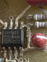
After cleaning with some denatured alcohol it's more clear now
After cleaning with some denatured alcohol it's more clear now
Attachments

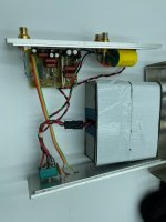
Is there a pic of he whole inside at once so we can get a idea of where all the close-ups are located relative to each other?
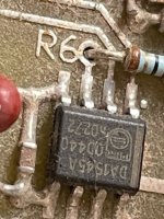
Kinda looks like the resistor R6 might not be soldered very well?
Probably a good idea to visually inspect all components, traces, solder joints, etc., for any signs of cracking or corrosion.
If visual inspection passes, then one of the other first things to do would be to check the power supply voltages. If you look up the data sheet for each chip based on the now legible part numbers, you can find out which pins are for power, signals, control, ground, etc. Might also make sense to check power with a scope too in case there is ripple or other problems that don't show up well on a DVM.
If we end up needing to do some signal tracing, how do you normally input digital data to this DAC? SPDIF, TOSLINK, USB, etc.?
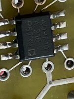
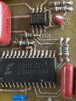
Pin 8 on the CS8414, pin3 on the dac chip and R6 are all worth checking - and that via near pin 7 of the dac chip?
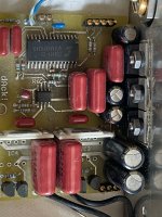
It is a CS8414, TDA1545A and a pair of op-amps. There are more complicated Lego sets.Is there a pic of he whole inside at once so we can get a idea of where all the close-ups are located relative to each other?

Since it isn't locking, continuity from the input connector to the caps and the CS8414 would be one place to start.Where do I start to fix it,
Gee, no power supply, no IO connectors, just four chips is all. Pretty slick.It is a CS8414, TDA1545A and a pair of op-amps. There are more complicated Lego sets.
Anyway, speaking of more complicated lego stuff:
Yeah. It could be a simple busted solder joint on the coax connector.Since it isn't locking, continuity from the input connector to the caps and the CS8414 would be one place to start.
Tom
Next after checking those solder points, I think you have to check DC voltages at power pins etc. Then next would be to check is the signal getting to the chips from the input.
And then see if you get MCLK and/or WS at the right frequency when providing the CS8414 with an input.
Tom
Tom
Its very nice that so many people are willing to chime in with some helpful tips. However, sometimes people can be a little reluctant to help in the beginning when its not clear if helping will suddenly become easy. Hopefully there will be more of trying to help people when you don't know if the OP can post clear pics, don't know if they have access to a scope, etc. Just sayin'
We were too poor to have lego while growing up,we did have meccano sets and I still would like to play again (sadly I just read that the factory in France is closing)
It's really a v simple and effective dac
Here is the link to the company
http://www.ack-industries.com/dAck!.html
And some reading about the guy that started it all
https://www.tnt-audio.com/intervis/kusunoki_e.html
I started collecting CDs since 82 and have a few that actually sound decent with this dac
Thank you all for chiming in I will do some resoldering,it's battery run at 12 v it's a tiny circuit board
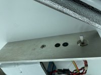
Some additional pictures
It's really a v simple and effective dac
Here is the link to the company
http://www.ack-industries.com/dAck!.html
And some reading about the guy that started it all
https://www.tnt-audio.com/intervis/kusunoki_e.html
I started collecting CDs since 82 and have a few that actually sound decent with this dac
Thank you all for chiming in I will do some resoldering,it's battery run at 12 v it's a tiny circuit board
Some additional pictures
Attachments
Good tips. Make sure to measure voltages first.
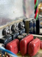
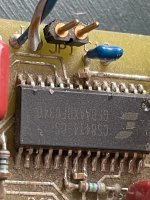
It would not surprise me if C4 would be kaputt. Drop type tantalums are famous for spectacular failures. Also the receiver CS8414 might have taken some ESD and possibly decided not to accept that. It happens.
It would not surprise me if C4 would be kaputt. Drop type tantalums are famous for spectacular failures. Also the receiver CS8414 might have taken some ESD and possibly decided not to accept that. It happens.
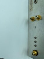
There are some spots that look suspicious in the pics. For example the pin in the orange box below doesn't look soldered. The green box shows an area that is obscured by some cleaning material, so can't tell if what's underneath looks okay.

Next pic shows possible capacitor leakage and pin without visible solder:

Next pic shows possible capacitor leakage and pin without visible solder:
Last edited:
Thanks jean paul had no idea that the tantalum is prone to failure,I will charge the battery overnight and start measuring,perhaps I am not getting full power from the battery pack,
Markw4 will solder those weak spots,although surprisingly it ran for almost 20 years with no issues
Incidentally the owner of the company contacted me and will try to fix it for a few $$
So I have a back up plan unlike stepping on lego in the night.
Markw4 will solder those weak spots,although surprisingly it ran for almost 20 years with no issues
Incidentally the owner of the company contacted me and will try to fix it for a few $$
So I have a back up plan unlike stepping on lego in the night.
- Home
- Source & Line
- Digital Line Level
- My old ack dack ,stopped locking to the coax source